New LED Trailer Lights Not Working Correctly? How to Separate Wiring, Ground and Lamp Faults
In this article
New LED trailer lights can be connected and still behave incorrectly. The running lights may work while the brake lights stay dark. One turn signal may flash on both sides. A lamp may look bright on a separate power supply but become dim when connected to the trailer.
The quickest way to identify the cause is to divide the installation into five test points: vehicle output, plug and socket, individual function wires, ground return, and the lamp itself. Check each point with the affected function operating. The place where a correct signal becomes incorrect identifies the section that needs attention.
A working tail light proves only that its own circuit can operate under those conditions. It does not verify the brake input, turn input, connector assignments or the ground path under a different load.
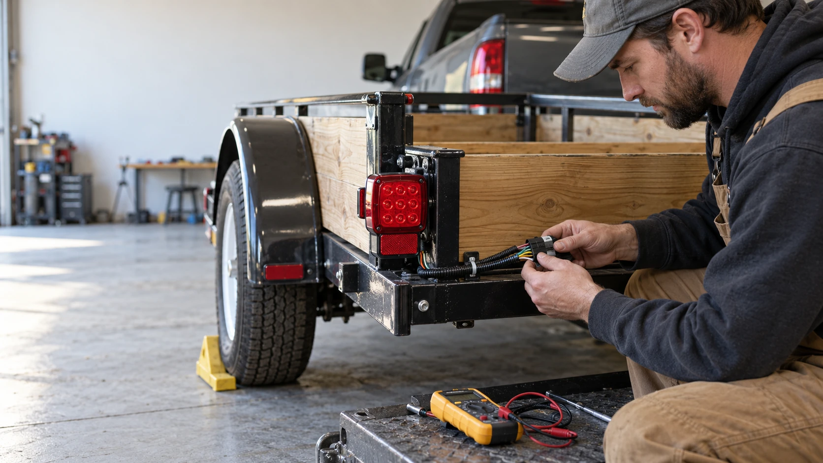
Start with the symptom, then follow the circuit
Before disconnecting anything, write down exactly what happens with running lights, brakes, left turn and right turn. Repeat the tests with the running lights switched on. That second round often reveals a connection problem that a single-function test misses.
| What you see | First useful comparison | What the result can tell you |
|---|---|---|
| No trailer lights work | Test vehicle socket outputs and socket ground | Establish whether usable signals reach the connection |
| Running lights work; brake lights do not | Compare brake and turn commands at the socket | Separate a missing command from a trailer-side fault |
| Brake lights work; running lights do not | Follow the tail/running feed from socket to lamp | Locate the interruption in that function |
| Only one side works | Compare the corresponding left and right circuits | Narrow the fault to an output, branch, connection or lamp |
| Lights dim when brakes are applied | Measure feed and ground voltage drop during the symptom | Identify a restriction that appears under combined load |
| Other lamps glow or flash unexpectedly | Check function assignments and the shared return | Separate crossed feeds from an inadequate ground path |
| A lamp fails on an isolated supply | Verify its specified terminals, polarity and voltage | Determine whether the fault remains with the assembly |
On a narrow screen, scroll the table horizontally.
These observations choose the next measurement. A dim lamp can result from restricted power, restricted ground or an internal fault; brightness alone does not identify which one.
Prepare a repeatable test
Park securely, apply the parking brake and chock the trailer wheels. Have a helper operate the controls so you can watch both rear lamps without moving the vehicle. Set the parking or running lights deliberately; daytime running lamps do not necessarily activate the trailer tail-light circuit.
Useful equipment includes the correct connector diagram, a digital multimeter, suitable connector test leads, a vehicle-compatible socket tester and an insulated temporary ground lead. An isolated lamp test also needs a DC supply of the lamp's specified voltage with suitable current limiting or a fused positive lead.
Use DC volts for live voltage measurements. Keep the meter leads in the voltage and common sockets. Resistance and continuity checks belong on disconnected, unpowered circuits. Use breakout leads where possible so probing does not spread terminals or puncture insulation.
Keep the setup consistent. Record whether the ignition is on, the engine is running and the trailer is connected. Change one condition at a time, then repeat the original failing combination after each repair.
Step 1: Verify the tow vehicle's actual trailer outputs
Disconnect the trailer and identify the vehicle socket's lighting terminals and ground terminal from its diagram. Test the vehicle output before tracing wires toward the rear lamps. Optronics' installation guidance likewise starts a total lighting failure by checking the vehicle trailer connection. Optronics installation troubleshooting.
Activate running lights, brakes and each turn signal separately. Use a compatible socket tester or measure each documented lighting output against the socket ground. Record whether the output is absent, steady or flashing as expected.
For a conventional North American four-way flat system, the functional pattern is:
| Vehicle command | Expected lighting outputs |
|---|---|
| Running lights on | Tail/running output energized |
| Brake pedal pressed | Both combined stop/turn outputs energized |
| Left turn selected | Left stop/turn output flashes |
| Right turn selected | Right stop/turn output flashes |
On a narrow screen, scroll the table horizontally.
The vehicle's own lamps can work while a trailer output fails. Trailer circuits may have their own fuses, supply wiring or converter. If an output is missing, follow the vehicle and towing-harness instructions for that circuit. A failed brake-light command at the socket cannot be repaired by changing a trailer lamp.
If several outputs appear missing when measured against socket ground, verify that return against a known-good vehicle negative reference. A faulty socket ground can make several healthy feeds appear absent.
Account for trailer detection on electronically controlled vehicles. Some modules need a recognized load before providing the expected output. An empty-socket reading or a small indicator tester may therefore need confirmation using the vehicle manufacturer's test procedure or an approved simulator.
Result: If a required output fails the correct vehicle-side test, stay on the vehicle side. If all outputs pass, continue to the connector. If they work disconnected but collapse with the trailer connected, investigate loading, a trailer short, supply or ground resistance, and module protection before blaming either side.
Step 2: Inspect the plug, socket and any adapter
A connector can fit mechanically while one contact barely touches. Disconnect power before opening or cleaning it. Look for water, green or white deposits, darkened contacts, bent pins, loose terminals and wires pulling out at the cable entry.
Inspect both mating halves. Cleaning the trailer plug will not repair a damaged vehicle socket. Check any adapter separately, including its ground contact and the terminals behind its housing.
Remove contamination using a connector-appropriate method and let the parts dry. Replace contacts that have lost their plating, grip or structural integrity. Corrosion can extend beneath insulation, so a clean-looking terminal on deteriorated wire may still need replacement.
Reconnect fully and repeat the failing function. If gently moving the stationary plug changes the symptom, inspect terminal retention and contact pressure. That response identifies an intermittent connection area; it does not tell you which terminal without further testing.
When suitable breakout access is available, compare voltage on the same function immediately before and after the connection while the lamp is operating. A loss concentrated across that contact points to the connector. Include the return contact in this comparison.
Protect repaired connections as specified by the connector manufacturer. Dielectric grease helps exclude moisture; it does not replace clean, tight metal contact or restore a corroded conductor. Use it in the locations and quantity appropriate to the connector design.
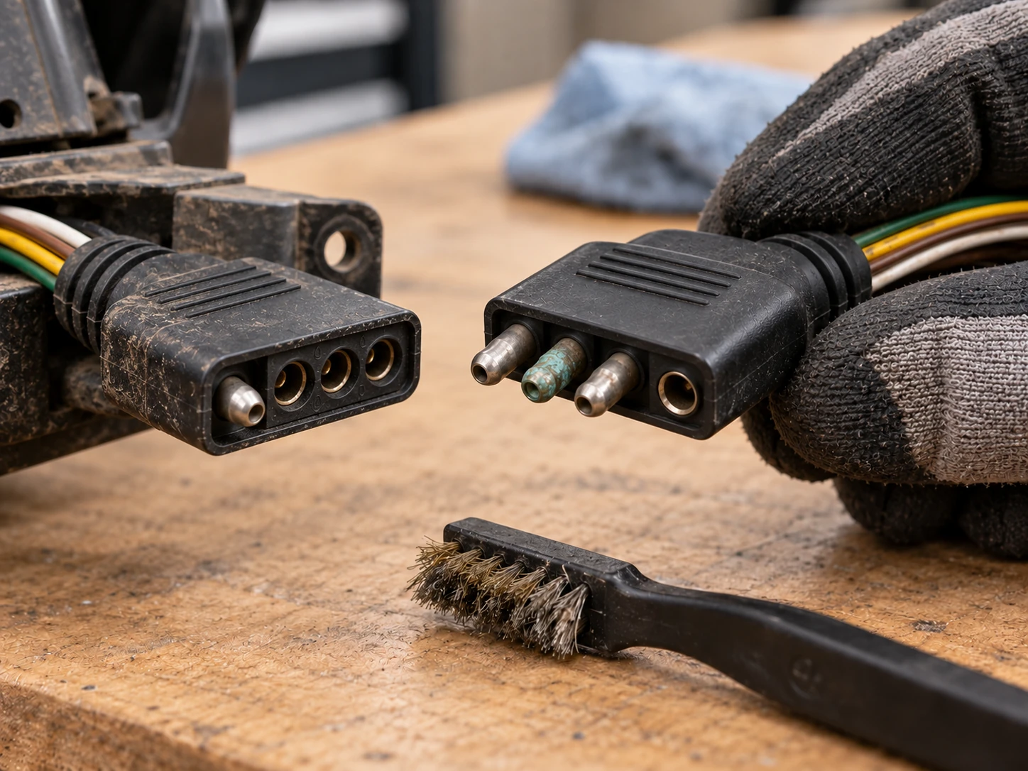
Result: If the signal is correct at the vehicle socket but incorrect immediately after the plug or adapter, repair that connection. If it remains correct, follow the affected function wire toward the lamp.
Step 3: Trace each lighting function, not just wire colors
Confirm what each conductor actually does. On a standard US four-way flat connection, white is ground, brown is tail/running, yellow is left stop/turn and green is right stop/turn. These assignments are documented in CURT's trailer wiring guide.
That chart describes a connector system. It does not establish every replacement lamp's wire colors. A lamp may use different colors or a molded connector with numbered terminals. Match the verified trailer function to the lamp's documented input.
Why four contacts may connect to more than four wires
The number of conductors does not always equal the number of functions. A harness can split one running-light circuit into left and right branches, or carry separate returns from several lamps. An earlier repair may have added another branch.
If a four-pin plug has seven wires behind it, identify where each wire goes before reconnecting it. With the system isolated, trace branches and label them by function. Several wires may legitimately share one function, but wire count alone cannot establish that.
When trailer brake lights work but running lights do not
Check the tail/running output at the socket, then at the plug exit, the next accessible junction and the lamp input. On a conventional four-way system, a working brake lamp does not verify the separate brown running-light feed.
If both rear running lights and the markers fail together, inspect their common supply section first. If the markers work and only one rear tail function fails, move toward that lamp's branch, connector and tail input.
When running lights work but brake lights do not
Check the stop/turn outputs during an actual brake command. Then compare turn operation. In the conventional combined system, a lamp's bright stop/turn input serves both braking and signaling on its side.
If that lamp flashes strongly for a turn but never responds to braking, its bright input has demonstrated operation during the turn test. Verify the vehicle's brake-command output and converter behavior before replacing the lamp. Confirm that the same bright function, rather than a crossed tail input, was actually flashing.
With brakes and a turn signal applied together, a conventional combined stop/turn system flashes the selected side while the opposite side maintains the brake indication. Separate brake-and-indicator systems need their own function chart. On a seven-way connector, the electric wheel-brake output is also a different circuit from the brake-light outputs.
When only one turn signal or one side fails
Compare the matching output at the vehicle socket and at the affected lamp. Correct voltage at the socket but missing voltage at the lamp points toward the intervening plug, splice or wire. A missing left output should not send you searching through the right-hand branch.
Where voltage arrives normally, continue to the return and lamp tests. A continuity beep on an isolated wire is useful for tracing, but it does not establish that a partly corroded connection will carry the operating load.
Result: Locate the last accessible point where the commanded function is correct and the first where it is wrong. Inspect the section between them. Recheck the whole function after repairing it.
Step 4: Test the complete ground return under load
Every lamp needs a return path to the supply negative. Depending on the installation, that path may use a dedicated wire, the trailer frame, or both. Follow it from the lamp through the trailer connection and vehicle return.
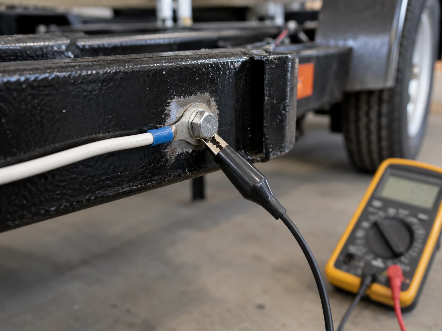
A ground terminal at the tongue does not automatically ground every lamp. Paint beneath a mounting terminal, a loose bracket, a corroded stud or an unreliable joint in a folding frame can interrupt the path farther back. A dedicated ground wire also needs sound connections at both ends.
Use a temporary return to test the suspected section
Connect an insulated jumper of suitable capacity from the lamp's identified ground terminal to a verified return point. Make connections with power off, secure the lead away from moving parts, and then repeat the failing function.
Choose the return point to answer a specific question. Connecting to a nearby frame point tests a different section from connecting to a verified return near the trailer connector. A point covered in paint or connected through the same suspect joint does not provide an independent comparison.
If the lamp returns to normal with the added return, the bypassed ground path needs attention. If nothing changes, continue checking the supply and lamp; the jumper result is only meaningful when both test connections are sound. Keep any direct battery-negative test lead clear of the engine and do not crank the engine through a temporary lighting-ground setup.
Measure the loss while the fault is happening
With the affected circuit drawing current, measure between the lamp ground terminal and the verified supply-negative reference. This measures loss along the return path. Measure the positive path separately, from the supply side of the affected feed to its lamp input.
Fluke explains that voltage-drop testing requires current flow: an unloaded circuit cannot reveal the same restrictions. Its general fallback guidance lists 0.10 V at a ground when equipment-specific limits are absent. Apply the vehicle and lamp specifications first, and assess each section rather than treating one number as a universal whole-trailer limit. Fluke voltage-drop testing guidance.
For illustration, suppose a steady feed measures 12.5 V against a verified negative reference, while the connected lamp's ground terminal measures 1.5 V against that same reference. Approximately 11.0 V remains across the lamp. The ground side is consuming part of the available voltage. These are example readings, not acceptance limits.
Move a probe along accessible return connections while maintaining the same load. A marked change across a joint helps locate the restriction. An open circuit with no current needs its interruption repaired before a meaningful loaded voltage-drop comparison can be completed.
Why lights become dim or interact when braking
Braking adds another operating condition. A marginal common return may carry one function adequately and then develop a larger loss with several lamps energized. LED assemblies can respond by dimming, flickering or switching off, depending on their electronics.
In some interconnected lamp circuits, a poor return also allows unintended current paths through another function. That can make a tail lamp react to a turn signal or make several lamps change together. Crossed wires or contaminated contacts can produce similar behavior.
Repeat the combination that triggers the problem while checking the return and the supposedly inactive function input. If restoring the return removes the interaction, that is useful evidence for a return fault. If the wrong input remains energized with a sound return, revisit the plug assignments and shared junctions.
How to ground trailer lights after finding the fault
Follow the lamp and harness design for the permanent repair. Connect a dedicated ground lead to the specified return circuit or designated grounding point. Where the design uses a frame connection, secure the terminal against sound contact metal and protect the completed joint against corrosion. Provide the specified bonding or dedicated return across folding and tilting sections. A lamp mounted in a rubber grommet or on a painted bracket may need its own return wire; its mounting position alone does not complete the circuit.
Result: A successful return bypass and an excessive loaded loss support a ground-path repair. A sound return with a disappearing feed directs attention back to the supply side. Correct conditions at the lamp lead to the isolated lamp test.
Step 5: Test the LED lamp independently
Disconnect the lamp from the trailer harness so the test supply cannot feed the vehicle module or another trailer circuit. Identify the assembly's ground, function inputs, rated voltage and polarity from its instructions.
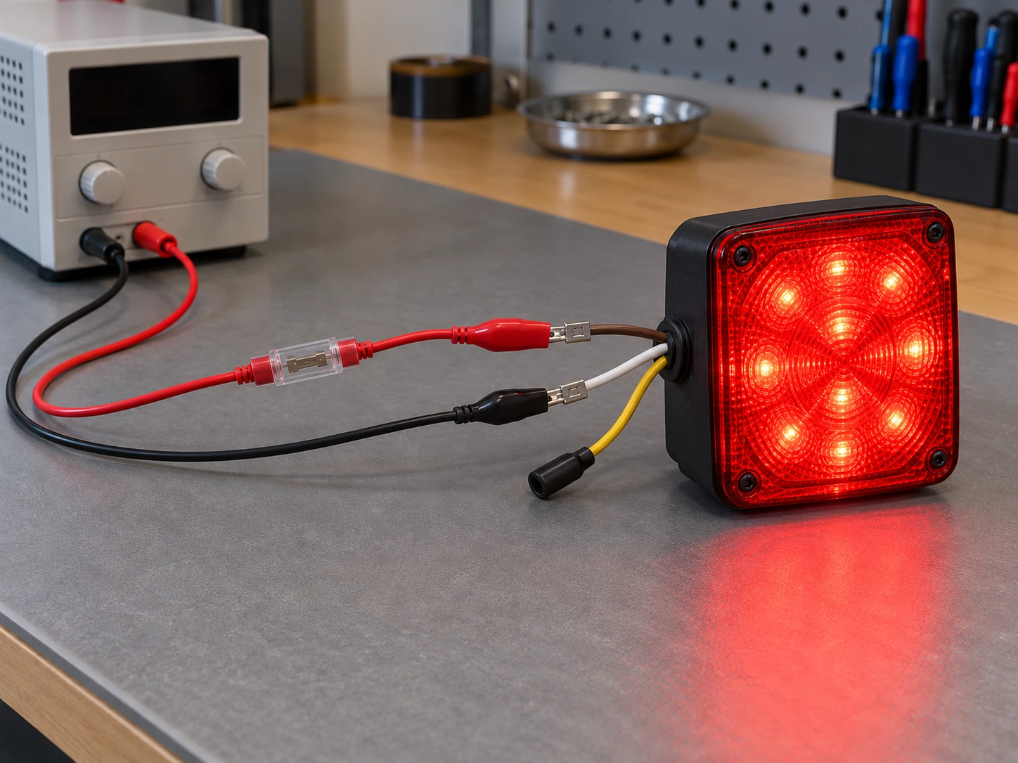
Use a stable DC supply at the specified voltage, with current limiting or a positive-lead fuse sized for the test wiring and lamp. A battery can provide the source when the setup includes that protection. An unspecified battery charger is a poor substitute for a suitable test supply.
Connect the lamp ground to supply negative. Apply protected positive power to one documented function input at a time. For a lamp designed with separate tail and bright stop/turn inputs, verify each input separately and confirm the intended brightness difference. Test simultaneous inputs only as its instructions allow.
Measure voltage at the lamp's actual connection while it operates. Correct voltage at the battery terminals does not establish correct voltage through a loose test clip or damaged pigtail.
This same method applies when installing a GOODIN 4-inch LED trailer light: use the supplied function and terminal information to test the particular assembly. Confirm those connections before applying test power.
Interpret the result carefully:
- Every specified function works independently: return to the trailer feed, return path, connector or vehicle compatibility.
- One specified function repeatedly fails: inspect its pigtail and terminal. With correct supply and return at the assembly, the lamp becomes the likely fault.
- A known-good matching lamp works on the same isolated setup: compare the suspect lamp on that unchanged setup. A failure that follows the assembly strengthens the diagnosis.
- The result changes when a test lead moves: repair the test connection before drawing a conclusion.
A new lamp can be faulty, but an isolated test gives a reason to replace it. It also prevents a damaged connector or missing input from being mistaken for a failed LED assembly.
Step 6: Check LED compatibility when the electrical paths pass
If the lamps work independently and the installed feeds and returns test correctly, investigate the vehicle's response to the LED load. Useful clues include rapid indicator flashing, a lamp-out warning, brief off-state flashes or a trailer-detection problem that began with the conversion.
HELLA documents trailer modules that monitor lighting loads and detect low-power LEDs. That means compatibility depends on the module and lamp combination, rather than simply whether both are described as LED compatible. HELLA trailer tow modules.
Follow the vehicle or towing-harness manufacturer's supported remedy. It may involve an appropriate module, an approved adapter or a specified configuration. A load resistor changes current draw and produces heat; its rating, installation and effect on failure detection need to match the intended application.
Avoid choosing a resistor just because a lamp flickers. A loose terminal can flicker too. Confirm that the commanded feed, return and independent lamp operation pass before treating the symptom as a compatibility issue.
For pulsed or electronically controlled outputs, a basic meter may display an average rather than the complete waveform. Compare readings using the manufacturer's procedure and appropriate equipment before interpreting that average as ordinary supply loss.
Adjust the wiring reference for your market
The diagnostic sequence stays useful across markets, but connector assignments must match the installation. The US four-way example also applies to many Canadian light trailers using that system. A seven-way connector needs its own diagram, including the correct contact-side or cable-entry view.
For UK towing installations, brake and indicator functions are commonly separate, and the left and right tail-light feeds may be separate too. Ryder's 13-pin guide identifies a dedicated brake terminal and separate left and right tail terminals. Ryder Towing 13-pin wiring guide.
Australian and New Zealand installations also require the diagram for their actual connector. Narva's Australian installation guide illustrates seven-pin round and flat kits, and tests tail lights, brakes and indicators together to check operation and earthing. Do not transfer the North American combined stop/turn arrangement to a locally wired connector. Narva trailer-light installation guide.
The practical rule is simple: identify the function and connector view before measuring or reconnecting a terminal. A physically similar plug or familiar wire color is not enough.
Finish the repair with the same tests that found it
Repair the identified section, then repeat the original symptom test. Use suitable automotive connections, restore sealing and strain relief, and support the harness so steering, suspension travel or trailer movement cannot pull it tight.
Run the final checks in a clear order:
- Running and marker lights alone.
- Brakes alone.
- Left turn, then right turn.
- Running lights with brakes.
- Running lights with each turn signal.
- Brakes with each turn signal, as the system is designed to operate.
- Hazards and other fitted lighting functions.
Watch both sides for stable brightness and unwanted interaction. Recheck the connector and repaired joints for an intermittent response when the stationary harness is gently moved. Remove temporary test leads before towing.
Frequently asked questions
Why do my trailer brake lights work but not my running lights?
On a conventional four-way system, running lights use a different feed from the combined stop/turn circuits. Check that feed at the vehicle socket and follow it to the lamp. Working brakes do not verify the tail input or its branch wiring.
Can a bad ground affect only one trailer light?
Yes. A shared return fault can affect several lamps, while a poor connection at one lamp can affect only that assembly. Compare a verified temporary return with the original path and test while the symptom is present.
Why do trailer lights become dim when the brakes are applied?
A restricted shared supply or return may lose more voltage during the combined load. Measure both paths while braking with the running lights on. If those conditions remain correct at the lamp, continue with its independent function test.
How can I test trailer lights with a battery?
Isolate the lamp from the trailer harness, confirm its rated voltage and terminal assignments, connect the ground to battery negative and use a suitably fused positive lead for each documented input. Evaluate the lamp only after verifying the connections under load.
When should I replace the LED lamp?
Replace or service the assembly when the failure remains with it on a verified, correctly rated isolated supply, with the intended input and return connected properly. If it works independently, resolve the installation or compatibility fault before fitting another lamp.
Trailer Tool Box Lid Won’t Close Properly: Mounting Distortion, Hinges or Gas Struts?
Related Article