Hot-Dip Galvanizing Changes the Part Before It Protects It: Why Venting, Drainage and Distortion Must Be Designed In
On this page

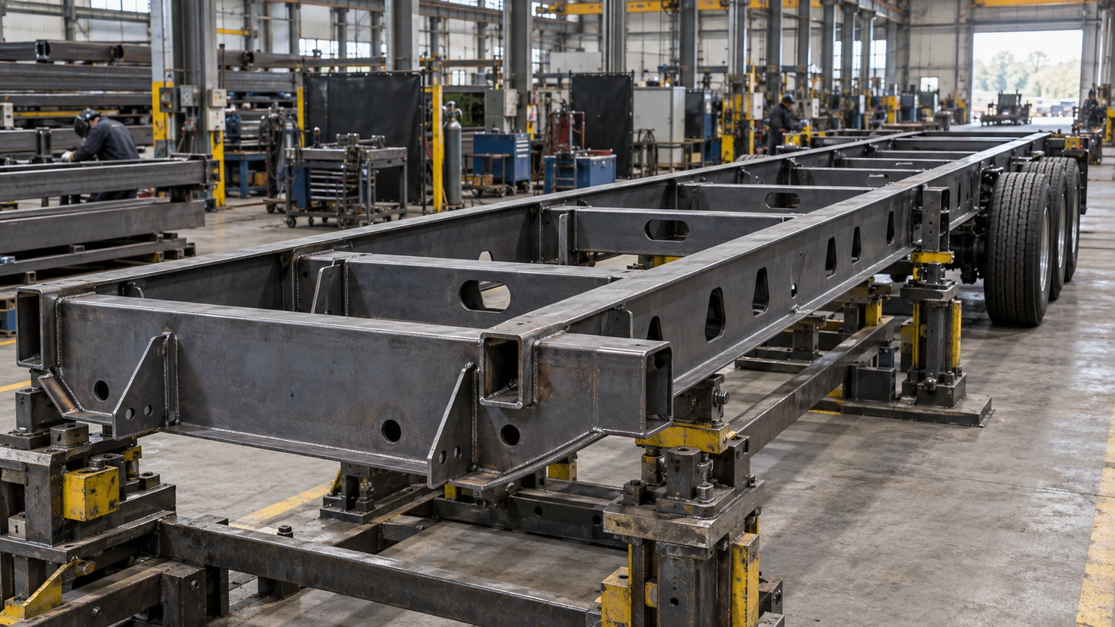
A galvanized trailer frame may look almost identical to a painted frame in a CAD model. The beams, cross-members and brackets can appear unchanged. Yet selecting hot-dip galvanizing introduces new engineering requirements: hollow sections need safe fluid paths, gussets must drain, and welded frames must retain acceptable geometry through a thermal cycle.
The coating also occupies space. A part that fits before galvanizing may not fit afterward. Corrosion protection therefore begins at the drawing board, not when a completed frame arrives at the galvanizer. The objective is a structure that can be processed safely, coated consistently and assembled correctly. [1]
Engineering analysis—not a vent-hole schedule, galvanizing operating procedure or approval to modify a load-bearing component.
Galvanizing Is a Manufacturing Process, Not Just a Finish
Hot-dip galvanizing involves immersing prepared steel in molten zinc, typically at approximately 450°C. Before reaching the zinc bath, fabricated steel undergoes surface preparation, which generally includes cleaning, pickling, rinsing and fluxing. The precise sequence depends on the galvanizing facility and the condition of the incoming material. During immersion, molten zinc reacts with properly prepared steel to form zinc-iron alloy layers, usually covered by a zinc-rich outer layer. The resulting coating provides barrier protection and sacrificial corrosion protection. However, the process requires more than exposing the outside of the component to zinc.
For a hollow steel member to receive internal protection, cleaning solutions and molten zinc must be able to enter the relevant cavity, contact the steel and subsequently drain out. The fabrication also experiences a substantial thermal cycle. Its final dimensions may change because of coating buildup, thermal distortion or the redistribution of stresses introduced during forming and welding. This creates three separate engineering requirements. The component must provide safe fluid access during processing. Its geometry must remain acceptable after heating and cooling. Finally, the zinc coating must not prevent the finished component from functioning.
A steel component can satisfy one requirement and fail another. For example, a trailer bracket may receive a compliant zinc coating but no longer fit its mating component. Alternatively, a frame may retain its dimensions but contain enclosed surfaces that could not be properly cleaned or galvanized. Coating quality, dimensional quality and functional quality must therefore be evaluated together.
The temperature is a typical process value, not a universal operating setting. Preparation, dipping, cooling and inspection must follow the agreed facility process and applicable material requirements. [15]
Design a Complete Venting and Drainage Path
Hollow steel sections are useful in drawbars, cross-members, perimeter frames and equipment supports. Their cavities, however, must be considered before galvanizing. A rectangular tube welded shut at both ends is not simply a protected void: heating expands the trapped air, while moisture or cleaning solution can rapidly become steam.
AGA warns that inadequate venting can lead to rupture and serious danger to personnel and equipment. This is a processing-safety requirement, not a cosmetic preference. A fabrication should not enter the process until its enclosed spaces and opening arrangement have been reviewed and accepted. [2]
Venting and drainage serve related but different functions. During immersion, air must leave so cleaning solutions and zinc can enter. During withdrawal, excess liquid must leave rather than remain trapped. A coating on the outside does not establish that the inside was accessible.
Air escapes → cleaning solutions and zinc enter → internal surfaces are exposed → excess liquid drains → the coating remains.
Restricting any part of this path can leave bare areas, retain zinc or trap pretreatment liquid. The requirement is a complete fluid path, not a hole placed wherever it is easiest to drill. Internal partitions and connections matter as much as visible openings.
Design for the suspended orientation
A trailer frame is rarely dipped in its road-going orientation. Kettle dimensions, lifting equipment, weight distribution and frame geometry determine how it is suspended. One end may enter before the other. The high and low points inside each cavity can therefore differ from those on a parked trailer.
AGA places vents at the high points and drains at the low points relative to the actual processing orientation. If a vent sits below an internal high corner, air can remain trapped above it. If a low corner cannot drain during withdrawal, zinc can remain there. A drawing that looks adequate with the tube horizontal may not represent the real process. [3]
Intersecting tubes complicate the review. A cross-member may connect to a longitudinal tube without an adequate internal passage. A diaphragm or end plate may create a separate volume. An opening in one compartment does not automatically vent the next. Show relevant internal connections and the intended handling arrangement before fabrication begins.
Square and rectangular members also cannot automatically adopt details developed for round tubes. Their corners create different high and low points as orientation changes. The actual shape and agreed suspension arrangement must guide the opening plan. [16]
Openings also change the structure
Making openings as small as possible can restrict flow, slow filling or withdrawal, and retain liquid. Making them larger without review can create another problem: lost net section, altered local stiffness or a fatigue-sensitive stress concentration near a loaded bracket or weld.
The appropriate arrangement depends on cavity size, length, geometry, interconnections and processing orientation. It also depends on the member’s load path. Drawbars, suspension regions and other repeatedly loaded details deserve particular attention; this article does not prescribe a universal hole diameter or allow workshop substitutions.
The designer and galvanizer must answer two questions together: can the fabrication be processed safely and effectively, and can the modified structure still meet its service requirements? Approval should address both. A process opening is an engineered feature, not an afterthought delegated to whoever receives the completed frame.

Gussets and Overlaps: Where Geometry Traps Liquid
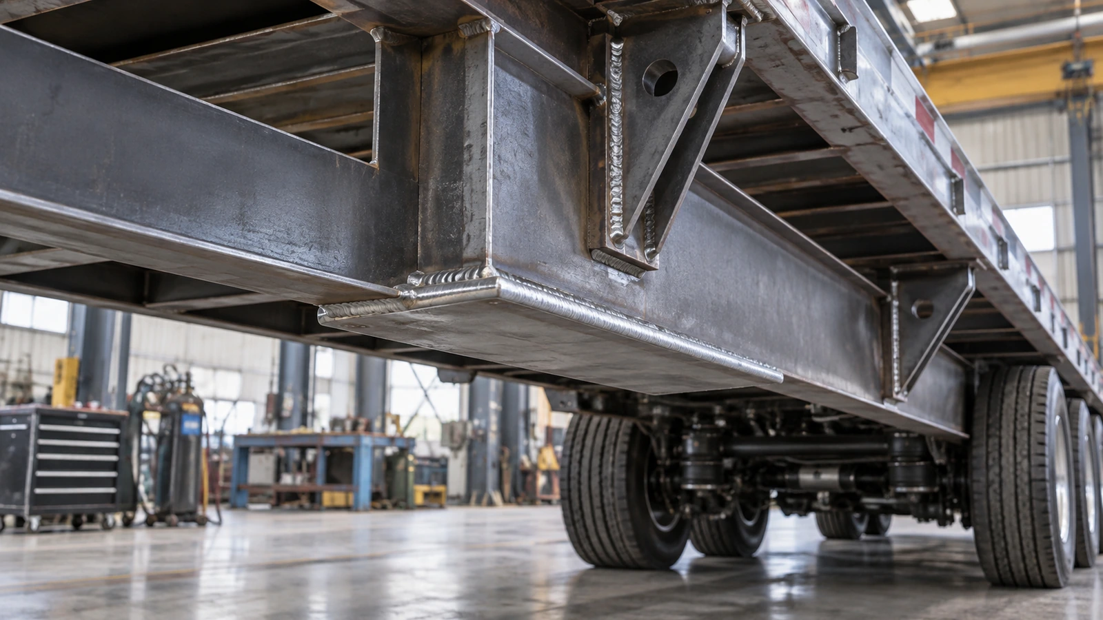
Gussets are introduced to reinforce connections, support brackets and transfer load between structural members. In trailer manufacturing, they appear around drawbars, cross-members, mounting structures and other connections. However, a gusset can also create a pocket. Imagine a triangular plate welded between a longitudinal chassis member and a cross-member. The plate strengthens the connection, but its geometry forms an enclosed corner. During galvanizing, the pocket fills with molten zinc. During withdrawal, the zinc cannot flow out freely. The trapped zinc may solidify, creating an unnecessary accumulation.
The consequences can include additional weight, increased zinc consumption, poor appearance and interference with nearby mounting or assembly surfaces. The AGA identifies gussets, stiffeners and end plates as common drainage-sensitive details. Its gusset and base-plate guidance [4] recommends appropriately cropped corners or strategically positioned openings to permit liquid flow. But cropping a gusset creates another engineering question. The plate was originally designed to carry load. Removing material changes its geometry. Depending on the connection, the modification may affect the net section, stiffness or local stress distribution.
A drainage opening could also create a new stress concentration if placed without considering the structural load path. The answer is not to avoid gussets. It is to design their structural and manufacturing functions together. Sometimes a cropped corner provides the required drainage without compromising the connection. Sometimes a different gusset shape is preferable. Sometimes the load path needs to be reconsidered. The best gusset is not simply the one that carries the greatest static load. It must also be manufacturable and compatible with the intended corrosion-protection process.
That principle applies equally to reinforcement plates, internal stiffeners and enclosed mounting brackets.
Overlapping Plates Create a Different Corrosion Problem
A hidden gap between two steel plates can be more difficult to galvanize than an open hollow tube. Consider a reinforcement plate welded onto a trailer frame. The two steel surfaces may be in close contact, but small gaps can remain. During pretreatment, cleaning solutions may enter those gaps. Molten zinc behaves differently. The AGA explains that cleaning chemicals can enter narrow gaps that molten zinc cannot effectively penetrate, particularly when the separation is less than approximately 2.5 mm. Its guidance on overlapped surfaces [5] explains how trapped pretreatment chemicals can subsequently cause staining or create safety risks during galvanizing.
The result can be an unfavorable sequence. Cleaning solutions enter the overlapping joint. The steel inside the gap is not adequately galvanized. Residual chemicals remain trapped. After the trailer enters service, moisture reaches the crevice. Corrosion products may eventually emerge around the edge of the reinforcement plate. The exterior coating can still be intact. Yet rust-colored staining appears around the welded connection. This is a useful example of why corrosion protection cannot be evaluated from visible coating thickness alone. The problem may originate in the geometry of an inaccessible internal surface. The appropriate response depends on the joint.
One option is an adequately executed seal weld that prevents chemicals from entering. Another is a suitable open-gap arrangement that allows cleaning solutions and zinc to enter and drain. For larger enclosed overlaps, appropriately designed venting may still be required even when the perimeter is seal-welded. Importantly, changing from a continuous structural weld to intermittent welding is not automatically acceptable. The connection must still satisfy its original structural requirements. This is where galvanizing design and fatigue design interact. A welding modification that improves drainage may change connection stiffness or fatigue behavior. The correct solution must satisfy both.

Control Distortion Before the Frame Reaches the Bath
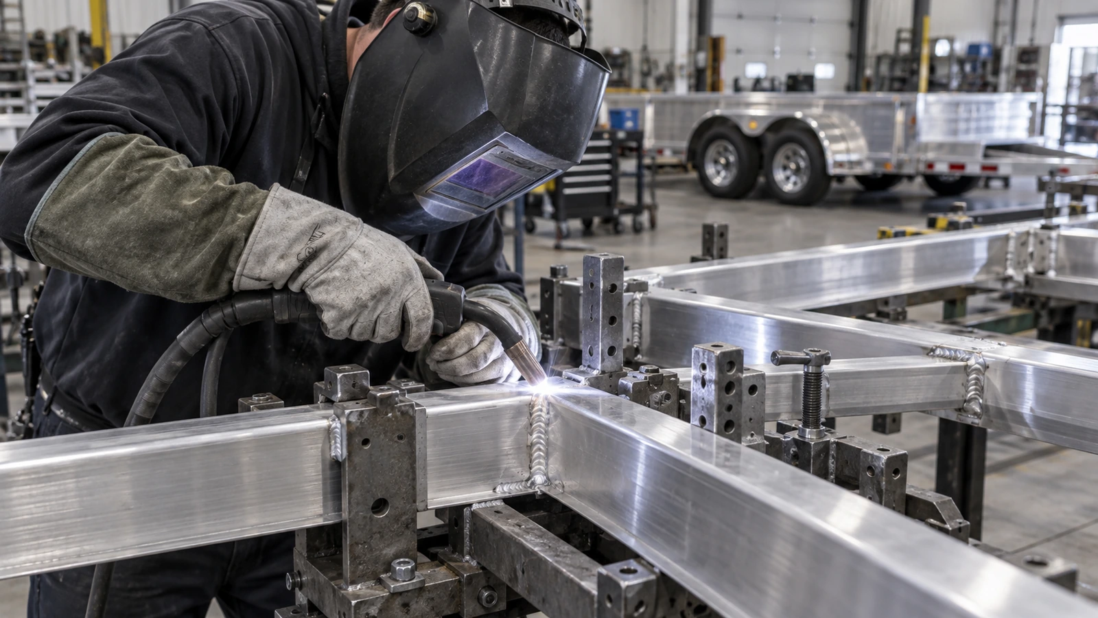
A trailer frame may meet every dimensional requirement before galvanizing and still require attention afterward. The reason is the thermal cycle. Steel expands when heated and contracts when cooled. If a uniform, unconstrained component heats and cools uniformly, much of that dimensional change is reversible. A welded trailer frame is more complicated. Its members may have different thicknesses. Some sections may be heavily welded. Other regions may contain thin plates or long unsupported members. The structure may also contain residual stresses created by forming, bending, straightening and welding. During galvanizing, different regions can heat and cool at different rates.
The resulting thermal expansion may be constrained by adjoining members. Existing residual stresses can redistribute. The completed assembly may therefore distort. The AGA's process-temperature guidance [6] identifies uneven heating and cooling, mixed material thicknesses, asymmetrical construction and fabrication stresses as important factors in galvanizing-related warpage. For a trailer, possible consequences include changes in frame straightness, cross-member alignment, mounting-hole position and local flatness. A large frame may bow or twist. A thin panel constrained between thicker members may become wavy. A mounting bracket may move outside its permitted positional tolerance. The coating may still satisfy its corrosion-protection specification.
But the component may no longer assemble correctly. The important distinction is that thermal distortion is not simply caused by the zinc bath being hot. It is caused by the interaction between temperature, geometry, restraint and the fabrication's previous manufacturing history. A structure with balanced geometry and controlled welding stresses may behave very differently from an asymmetrical fabrication containing large residual stresses. That is why distortion prevention begins before galvanizing.
Distortion Control Begins With the Original Fabrication
When distortion appears, the first instinct may be to ask the galvanizer to adjust the dipping process. Process control can help. The galvanizer may review immersion speed, orientation, handling and cooling practices. However, process adjustments have limits. If a frame combines very thin unsupported plates with thick structural members, its geometry may already be sensitive to uneven heating. If a welded assembly has been forced into alignment during fabrication, significant residual stresses may already exist. If the structure is highly asymmetrical, the temperature cycle may produce uneven dimensional changes.
The AGA's guidance on avoiding warpage and distortion [7] discusses these factors and highlights the importance of considering geometry and fabrication methods before galvanizing. For trailer OEMs, the recommendations translate into several engineering decisions. A large sheet-metal attachment may be better assembled after galvanizing rather than welded into a thick chassis beforehand. A thin mounting structure may require temporary bracing during processing. A long fabrication may benefit from a different suspension arrangement. A highly constrained welded connection may require a revised fabrication sequence. However, temporary bracing and structural modifications must be designed and approved appropriately.
An arbitrary stiffener can introduce new welding stresses or interfere with drainage. Likewise, post-galvanizing straightening should not become an uncontrolled substitute for dimensional design. The correct objective is to produce acceptable geometry repeatably. Not simply to repair every frame after it leaves the zinc bath.

Match the Trailer Design to the Galvanizing Route
A 45-foot custom RV frame
AGA describes a Wack Manufacturing custom RV trailer frame approximately 45 feet long and 8 feet 6 inches wide. The fabricator coordinated with the galvanizer before and during construction and attended the operation. Available single-dip capacity helped manage distortion concerns and coat the complete structure. [8]
This is evidence of early coordination, not proof that every frame requires one dip or that distortion cannot occur. Kettle size and handling capability belong in the original design review. A frame that fits a welding fixture may not fit the available kettle, and fitting inside the kettle does not by itself establish an acceptable processing orientation.
One-Piece Galvanizing and Modular Construction Solve Different Problems
This leads to a broader design question. Should a trailer frame be fully welded before galvanizing, or should it be manufactured as smaller galvanized subassemblies? A one-piece structure can reduce post-galvanizing connections. It may preserve the original welded assembly and simplify certain final assembly operations. However, large fabrications require appropriate kettle dimensions, lifting capacity and handling arrangements. Their cavities, stiffeners and mounting structures must also provide suitable fluid access in the selected dipping orientation. Modular construction introduces different advantages and constraints. Smaller parts may be easier to immerse, handle and drain.
Distortion-sensitive thin components can sometimes be galvanized separately from heavier structural members. The assemblies can then be joined afterward. However, the OEM must account for bolted connections, alignment tolerances, additional assembly operations and any coating restoration required after subsequent welding. Progressive dipping offers another possibility for fabrications too large for complete immersion. Progressive dipping also needs a distortion review because different portions of the structure undergo heating and cooling at different times. [6] [7] Its size and shape guidance [9] recommends considering kettle capacity and material handling early in the design process.
These alternatives should be compared according to the actual manufacturing route. The relevant question is not simply which method produces a galvanized surface. It is which combination of fabrication, galvanizing and final assembly delivers the required structure consistently and economically.
The Felling FT-80-3 project
The AGA’s Felling FT-80-3 report documents a trailer galvanized in 2012 for service involving road salt and calcium chloride. Felling’s engineering team worked with the galvanizer early to address venting around gussets, stiffeners and pockets. The more-than-52-foot fabrication challenged the plant’s capacity but could be accommodated in a single dip. [10]
The case connects substantial load-bearing members with the fluid-flow requirements they create. It does not justify deleting gussets or drilling arbitrary holes after fabrication. The Wack and Felling reports are industry-association project records, not independent comparative tests or universal guarantees.
Specify the Finished Clearance, Not Just the Bare-Steel Fit
The third major engineering issue appears after the fabrication has been successfully galvanized. The zinc coating occupies physical space. For a large chassis member, the additional thickness may be small relative to the overall dimensions. For a moving or closely fitted component, it can become important. Consider the interaction between a trailer jack's outer tube and inner telescoping tube. Before galvanizing, the tubes have a designed clearance. The fabricated dimensions already reflect material tolerances, forming variation and any welding distortion. If the relevant surfaces are subsequently galvanized, zinc buildup changes the available clearance.
The result can be a component that fits before processing but binds afterward. The AGA explicitly addresses this issue in its guidance for threaded and moving parts [11], recommending allowance for the coating and separate galvanizing of movable components where practical. For a trailer jack, the complete dimensional chain is:
Tube dimensions → forming tolerance → welding distortion → coating buildup → assembly clearance → telescoping performance.
That chain matters more than coating thickness in isolation. A well-galvanized component that cannot telescope freely has not met its complete functional requirement. The same issue can occur with mounting holes, hinges, sliding brackets, pins and threaded connections. The appropriate solution depends on the actual product. A mounting hole may require an approved clearance allowance. A threaded connection may require an appropriate post-galvanizing thread strategy. A moving assembly may need to be separated into components that are galvanized individually. A critical surface may require a different treatment or manufacturing sequence.
What should be avoided is uncontrolled grinding or machining after galvanizing simply to force an incorrect fit. Such operations can remove zinc and expose the underlying steel. The better approach is to establish the required final dimensions before fabrication and coating.
A Trailer Jack Should Not Necessarily Be Galvanized as a Complete Mechanism
This distinction is especially important for products containing both structural steel and precision mechanical components. A welded jack mounting bracket may be an appropriate candidate for hot-dip galvanizing. An outer structural tube may also be suitable when its geometry and coating requirements have been correctly designed. However, a complete trailer jack can contain gears, bearings, seals, grease, threaded mechanisms and other components that require a different manufacturing route. Those parts should not automatically be treated as a single galvanizing assembly. The correct approach may be to galvanize suitable steel fabrications first and install the mechanical components afterward.
This is a design decision, not a universal prohibition against galvanizing jack parts. Different jack designs use different materials, mechanisms and surface treatments. The important requirement is that the coating process must be compatible with the actual assembly. A procurement specification that simply requires every steel part of a jack to be hot-dip galvanized may overlook the functional requirements of the finished mechanism. A better specification identifies which components are galvanized, when galvanizing occurs and what dimensions must be maintained afterward. That is how corrosion protection becomes compatible with mechanical performance.

Plan Service Drainage, Steel Chemistry and Final Assembly
Another easily overlooked issue appears when the trailer enters service. The openings used during galvanizing were positioned according to the fabrication's orientation inside the zinc bath. The trailer is subsequently assembled and returned to its normal operating orientation. Rainwater, road spray and wash water now encounter a different geometry. An opening that allowed zinc to drain during processing may face upward during normal use. An opening located at the highest point during immersion may become a low point when the trailer is parked. Consequently, process openings and service drainage openings should not automatically be treated as interchangeable.
The engineering team needs to determine whether a process opening should remain open, be plugged or be incorporated into a separate service-drainage strategy. The AGA notes that vent holes may be left open or closed with suitable plugs after galvanizing. For boat trailers, the distinction is particularly important. The structure may be exposed repeatedly to water. The manufacturer should consider whether water can enter a hollow member, whether it can leave and whether any retained moisture creates an undesirable service condition. A hollow section that was successfully galvanized internally may still benefit from a deliberate drainage and maintenance strategy.
However, process openings should not be sealed without understanding their function in the finished product. The correct decision depends on the component geometry, service environment and intended maintenance requirements. Manufacturing drainage and service drainage are two different engineering problems. Both should be resolved before the final drawing is approved.
Steel Chemistry Can Change the Finished Coating
The galvanizing process also interacts with the chemical composition of the steel. Silicon and phosphorus can influence the reaction between steel and molten zinc. Certain steel compositions are more reactive and may produce thicker zinc-iron alloy layers. This can result in a coating that appears matte gray, mottled or less shiny than another galvanized component. The AGA explains these effects in its technical guidance on galvanized coating appearance [12]. For trailer procurement, the consequence is significant. Two suppliers may provide steel that meets the same basic structural grade requirement. However, differences in material chemistry can influence how the coating forms.
Weld-metal chemistry can also affect local coating appearance and buildup around welded connections. If a buyer requires highly consistent appearance across an assembled product, these material differences may need to be considered before steel is purchased. However, a shiny appearance should not be confused with superior corrosion protection. Similarly, a thicker coating does not automatically mean that every aspect of the finished component is better. The important questions are whether the coating satisfies the applicable specification, whether it is suitable for the service environment and whether its thickness and surface condition are compatible with the intended assembly.
This is another example of how the steel specification and coating specification interact. They cannot always be optimized independently.
Post-Galvanizing Rework Can Undo Part of the Protection
A poorly coordinated manufacturing sequence often reveals itself during final assembly. Suppose a trailer frame is galvanized and returned to the factory. A mounting hole is undersized. The operator drills it larger. A jack mounting bracket no longer aligns correctly. The operator grinds the contact surface. An additional attachment is required. The operator welds it onto the galvanized frame. Each modification can remove or damage the zinc coating. The finished trailer may contain exposed steel even though the original fabrication passed galvanizing inspection.
ASTM A780 provides methods for repairing damaged or uncoated galvanized surfaces, including zinc-rich paint, zinc-based solder and zinc-spray metallizing. The AGA discusses these options in its guidance on repairing damaged galvanized coatings [13]. These are legitimate repair methods when appropriately specified and applied. However, their availability should not make uncontrolled post-galvanizing modification the normal manufacturing strategy. The better approach is to anticipate mounting holes, clearances, joining requirements and final assembly operations before galvanizing. If post-galvanizing welding is unavoidable, the welding procedure, structural implications and coating-restoration method should be established in advance.
The objective is not simply to deliver a properly galvanized part from the coating plant. It is to preserve corrosion protection throughout final assembly.
Repair is not identical to recreating the original immersed coating. Agree the permissible repair scope, preparation and acceptance requirements rather than assuming any zinc-rich paint makes subsequent damage irrelevant. [13]
Acceptance Requires Coating, Dimensional and Functional Checks
A galvanizing supplier may provide coating-thickness measurements showing that a fabrication meets the required standard. That information is valuable. It does not prove that the entire trailer component meets every design requirement. Consider four different outcomes. A frame has adequate zinc thickness but unacceptable distortion. A hollow tube has a compliant exterior coating but an inaccessible internal compartment. A mounting bracket has good corrosion protection but excessive zinc buildup on a critical mating surface. A reinforced joint develops rust staining because chemicals were trapped in a narrow overlap. These are different problems.
A thickness gauge does not identify all of them. The applicable galvanizing standard establishes coating requirements, while the component drawing and assembly specification establish other acceptance criteria. ASTM A123/A123M addresses hot-dip zinc coating requirements for fabricated iron and steel products, including coating thickness, finish, appearance and adherence. However, compliance with the coating standard does not replace the need for dimensional and functional inspection. For a complex trailer component, an appropriate acceptance plan may therefore include coating verification, dimensional measurements, visual inspection of drainage-sensitive areas and functional checks of moving or mating components.
The inspection requirements should follow the product's actual failure risks. A simple open steel bracket does not require the same inspection plan as a long welded trailer frame or telescopic jack assembly. The test must measure the property the buyer actually needs to control.
The Relevant ASTM Standards Have Different Responsibilities
Several ASTM standards may be relevant to hot-dip galvanized trailer components. They do not all serve the same purpose.
| Standard | Primary role |
|---|---|
| ASTM A123/A123M | Hot-dip zinc coating requirements for fabricated iron and steel products |
| ASTM A153/A153M | Hot-dip galvanizing requirements for applicable iron and steel hardware |
| ASTM A385/A385M | Design and fabrication practices supporting high-quality galvanizing, including venting and drainage |
| ASTM A384/A384M | Practices for reducing warpage and distortion during galvanizing |
| ASTM A780/A780M | Repair of damaged or uncoated galvanized surfaces |
The roles of these standards are summarized in the AGA's ASTM specifications guidance [14]. The applicable specification and edition should be confirmed for the product and purchasing contract. The distinction matters because an OEM cannot rely on ASTM A123 alone to answer every engineering question about a complicated welded frame. The coating standard does not replace the structural drawing. The design guidance does not replace approval of a load-bearing modification. And coating repair procedures do not automatically establish that a modified component remains structurally acceptable. A suitable procurement package connects these requirements.
It specifies the intended structure, the appropriate coating and the finished condition that must be achieved.
What OEMs Should Resolve Before Releasing the Drawing
For trailer OEMs, the most important improvement is to establish galvanizing readiness before fabrication begins. The design review should examine the actual geometry being sent to the galvanizer. Every enclosed cavity needs an appropriate processing strategy. Internal diaphragms and intersecting tubes should be evaluated for adequate fluid access. Gussets and reinforcement plates should be checked for potential zinc traps. Overlapping surfaces should have an approved welding and venting arrangement. Large structures should be evaluated against the available galvanizing equipment. Distortion-sensitive assemblies should have appropriate geometric and manufacturing controls.
Critical holes, moving parts and mating surfaces should be designed around their final coated dimensions. These issues are connected. For example, moving a vent hole may improve zinc flow but place the opening in a fatigue-sensitive region. Changing a continuous weld may improve access to a crevice but alter the original structural connection. Separating a large frame into smaller galvanizing modules may reduce processing difficulties while introducing additional assembly requirements. The engineering team must evaluate those trade-offs together.
The AGA recommends early coordination between specifiers, designers, fabricators and galvanizers to resolve venting, drainage, lifting, size, steel chemistry and other process requirements. That coordination should produce agreed manufacturing details rather than rely on assumptions after the frame reaches the galvanizing plant.
What Procurement Teams Should Actually Specify
A request that simply states "hot-dip galvanized" may be adequate for some uncomplicated components. For complex trailer fabrications, it may leave important requirements undefined. The RFQ should identify the intended product, applicable coating specification and any design details that affect processing. For hollow steel structures, procurement should establish who is responsible for approving vent and drain locations. For large frames, the supplier should confirm the available kettle dimensions and handling capabilities. For distortion-sensitive components, the drawing should define acceptable final geometry. For moving assemblies, the required clearances should apply to the finished coated condition.
For parts assembled after galvanizing, the specification should identify any necessary coating restoration and final inspection requirements. The key is to distinguish between the incoming material, the galvanizing process and the finished component. A steel material certificate confirms specified properties of the incoming material. A galvanizing certificate or inspection record addresses the coating. Neither automatically verifies final dimensional accuracy, assembly fit or structural performance. Those requirements need their own acceptance criteria. A useful sourcing specification therefore controls the complete manufacturing outcome, rather than relying on a single coating description.
GOODIN View: Galvanizing Starts at the Drawing Board
A successful prototype does not guarantee that every subsequent production batch will behave identically. A trailer manufacturer may validate one frame using a particular galvanizing facility and dipping arrangement. Later, a production change introduces a different tube size, gusset geometry or internal reinforcement. The original venting arrangement may no longer be adequate. A different galvanizing facility may require another dipping orientation. Changes in steel thickness or welding sequence may alter distortion behavior. Even seemingly minor drawing revisions can therefore influence the galvanizing process.
For process-sensitive components, the approved venting arrangement, relevant drawing revision, handling requirements and dimensional acceptance criteria should be communicated to the galvanizer. Changes affecting these features should trigger an appropriate engineering review. This is not a requirement to prescribe every operational detail for every simple component. It is a way to ensure that the manufacturing process remains compatible with the product design. A component that can be galvanized successfully once is not necessarily a component that can be galvanized consistently at production scale.
That distinction is particularly important for OEMs producing hundreds or thousands of trailer components with repeatable dimensional and functional requirements.
Design the finished product, not only the coating
Hot-dip galvanizing can protect suitable trailer structures in demanding environments, but its success depends on the process that creates the coating. Hollow members need safe venting; gussets and brackets need drainage; overlaps need an approved access and welding strategy. Long frames need dimensional control, moving parts need clearance, and final assembly must preserve the protection.
Finalizing the structure first and adding “galvanized” as a finishing note can leave inaccessible cavities, zinc traps and incompatible fits. Correcting them later can require cutting, drilling, welding and reinspection. Early collaboration lets the engineer establish the load path, process openings, handling plan and final dimensions together.
GOODIN View: Galvanizing is not a finish selected after engineering is complete. For complex trailer components, it is part of the engineering input.
That principle applies to trailer jacks and mounting hardware and accessories: identify the steel fabrications suitable for galvanizing, protect the required interfaces, and define the subsequent mechanical assembly. A coating certificate alone does not approve a complete mechanism.
For an OEM program, discuss the OEM requirements with GOODIN with the load requirements, fabrication drawing, service environment and final-fit criteria. The target is a product that can be manufactured safely, coated consistently and assembled correctly—not merely a surface with a high zinc reading.
Sources & Further Reading
AGA guidance explains design principles; project reports are not independent comparative tests. Confirm the applicable standard edition, actual fabrication and processing plan with the responsible engineer and galvanizer.
- American Galvanizers Association — Design & Fabrication
- American Galvanizers Association — Venting & Drainage
- American Galvanizers Association — Hollow Structures
- American Galvanizers Association — Gusset and Base Plates
- American Galvanizers Association — Overlapped Surfaces
- American Galvanizers Association — Process Temperature
- American Galvanizers Association — Design of Products to Be Hot-Dip Galvanized After Fabrication
- American Galvanizers Association — Custom RV Trailer
- American Galvanizers Association — Size & Shape
- American Galvanizers Association — Felling Trailers FT-80-3 Trailer
- American Galvanizers Association — Threaded & Moving Parts
- American Galvanizers Association — Reasons for Different Appearances
- American Galvanizers Association — Repairing Damaged or Uncoated Areas of Hot-Dip Galvanized Coatings
- American Galvanizers Association — ASTM Specifications
- American Galvanizers Association — Hot-Dip Galvanizing (HDG)
- American Galvanizers Association — Venting and Drainage Holes in Square and Circular Tubular Assemblies
Stronger Steel Does Not Automatically Make a Better Trailer: The Hidden Design Changes Behind High-Strength Steel
Related Article