Same Load Rating, Different Product: Why Two Trailer Jacks With the Same Specification Can Perform Very Differently
On this page
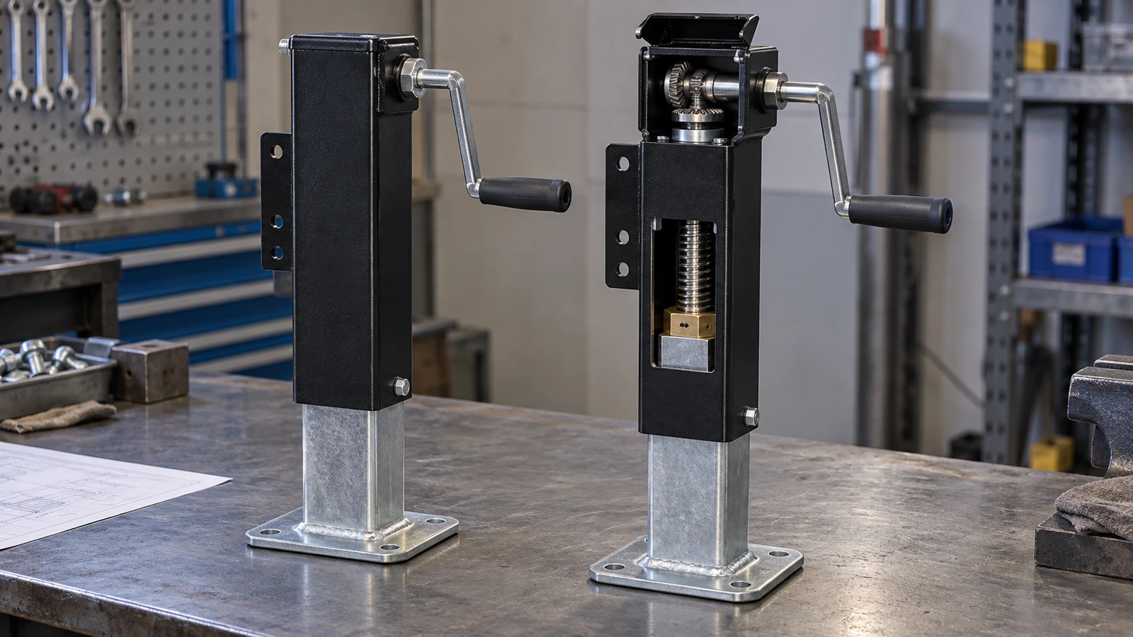
Two trailer jacks may carry the same 3,500 lb load rating, yet differ substantially in operating effort, smoothness, durability and manufacturing consistency. The key is to distinguish rated capacity from the complete mechanical performance of the jack. A load rating does not, by itself, describe screw efficiency, tube alignment, bearing condition, gear quality, lubrication, corrosion protection or how consistently those properties are maintained across production batches.
This article will follow those variables from component manufacture through assembly and actual use, with particular attention to the problems buyers encounter: increasing crank effort, binding near full extension, internal corrosion and premature gear or screw wear. The central GOODIN judgment is: A load rating defines a capacity threshold. It does not define manufacturing quality.
Engineering feature · Materials & Manufacturing
Start by Comparing the Same Capacity
Before comparing manufacturing quality, the first distinction is what the advertised capacity actually measures. A jack may have separate lifting and static support ratings. Lippert's technical guidance explains that lifting capacity describes the load the jack can raise, while support capacity describes the load it can hold while stationary. For example, BULLDOG specifies 10,000 lb lifting capacity and 12,000 lb support capacity for certain heavy-duty square jacks, including Model 182524. [1] [2]
That means even two products advertised with the same prominent capacity number may not have equivalent operating ratings. Buyers must first confirm that they are comparing the same type of capacity, the same intended application and the same operating conditions. Once those specifications are aligned, the deeper manufacturing question begins. Two jacks can satisfy the same lifting requirement while using different screw geometries, gear arrangements, tube tolerances, bearings and lubrication systems. Those differences can affect how much effort is required to operate the jack, how smoothly it travels and how its performance changes with use.
The rating establishes an important requirement. It does not describe the entire mechanism.
Tube Geometry: Where Tolerances Become Friction
Outer Tube Straightness
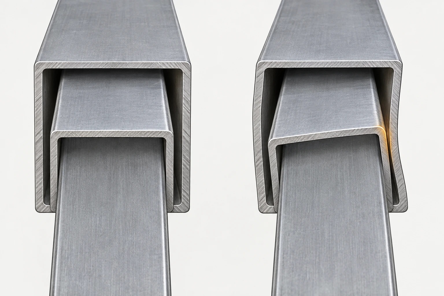
A telescopic jack relies on the relationship between its outer tube and inner moving leg. The outer tube provides the structural housing and connects the mechanism to the trailer. The inner tube moves vertically to raise or lower the tongue. For the assembly to operate smoothly, the two parts need compatible geometry. The outer tube must have acceptable straightness. The inner tube must fit without excessive interference.
The moving surfaces need enough clearance to accommodate normal manufacturing variation without creating unnecessary looseness. Now consider two nominally identical jacks. Both use steel tubes of the same nominal dimensions. Both satisfy their specified lifting capacities. In one jack, the outer tube is straight and the inner leg moves freely throughout its travel. In the other, a slight bend in the outer tube reduces clearance in one region.
The second jack may still lift its rated load. However, the moving leg can experience additional contact pressure against the housing. That contact creates friction. The user must apply more crank torque to overcome it. Repeated sliding under unfavorable contact conditions may also accelerate wear or damage the protective coating on the contacting surfaces. The important point is that a small geometric variation can change the operating experience without immediately causing a static structural failure.
The jack can meet its load rating while delivering noticeably poorer movement quality. For procurement teams, nominal tube dimensions alone do not establish the necessary geometry. Straightness and the relationship between mating components may be equally important.
Controlled Clearance, Not Maximum Clearance
If insufficient clearance creates binding, a manufacturer might respond by increasing the gap between the inner and outer tubes. That can improve assembly freedom. It can also create another problem. A jack leg must remain adequately guided while carrying load. Excessive clearance allows greater relative movement between the telescoping members. Under an off-center load, the inner leg may tilt within the outer tube until it contacts the guide surfaces.
That can increase local contact pressure and introduce additional bending or side loads into the mechanism. The jack may feel loose when unloaded but become difficult to operate when supporting the trailer. There is therefore a trade-off. Insufficient clearance can cause binding. Excessive clearance can increase movement, misalignment and localized contact. The appropriate clearance depends on tube geometry, overlap length, manufacturing tolerances, coating condition and the loading the jack is designed to accommodate.
This is especially important for wheeled swivel jacks. When a user attempts to move a trailer by hand, the wheel encounters rolling resistance and may experience lateral forces. Those forces can enter the telescoping structure. A jack intended for primarily vertical lifting should not be assumed to tolerate arbitrary side loading merely because its vertical capacity is sufficient. The designer must consider the complete operating condition.
Good telescoping performance requires controlled clearance, not maximum clearance.
Tolerance Stack-Up
A production problem becomes more difficult when every individual component appears to meet its drawing. Suppose the outer tube is within its dimensional tolerance. The inner tube is also within tolerance. The mounting bracket meets its specification. The nut and screw are manufactured within their respective limits. Yet the completed jack binds. This can occur because the deviations interact. Consider a simplified dimensional chain. The outer tube is near the small end of its permitted internal dimension.
The inner tube is near the large end of its permitted external dimension. The outer tube has a small straightness deviation. The inner tube has a small angular deviation. Welding introduces additional local distortion. A surface treatment changes the dimensions of the sliding interface. Every variation may be individually acceptable. Their combined effect may still consume too much of the available operating clearance. This is tolerance stack-up.
It explains why specifying every component independently is not always sufficient. The manufacturer must also evaluate how those components fit together under the least favorable permitted combinations. For a square jack, this can involve several geometric relationships: The straightness of each tube, its cross-sectional dimensions, the squareness of the section and the relationship between the tube and its mounting features. For a round jack, relevant properties may include straightness, roundness and alignment of the mating cylindrical features.
Coaxiality or concentricity may be relevant to particular internal designs, but those terms should not be applied indiscriminately to square telescoping tubes. The relevant requirement is the geometry necessary for the mechanism to function. A collection of individually acceptable parts does not automatically produce an acceptable assembly. This is why the finished jack needs dimensional and functional verification rather than relying exclusively on incoming component inspection.
Inside the Mechanism: Screw, Nut, Gears and Bearings
Lead, Mechanical Advantage and Friction
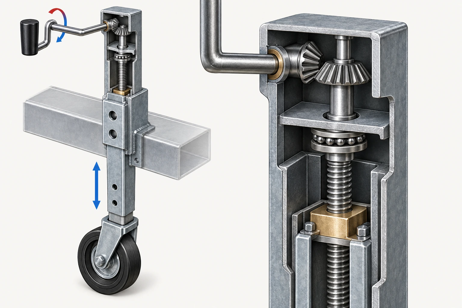
The telescoping tubes provide structural guidance. The screw mechanism produces the vertical movement. In a conventional screw-driven trailer jack, rotating the input drives a threaded screw relative to a nut. Depending on the design, the screw or nut is restrained axially while the other member moves with the telescoping leg. The thread converts rotational motion into linear movement. Its geometry determines how far the leg moves for each revolution of the screw.
Its friction characteristics influence the torque required to move a particular load. The mechanical relationship is straightforward: A screw with a greater lead produces more linear travel per screw revolution. A smaller lead provides more mechanical advantage under otherwise comparable conditions, although more revolutions are needed to cover the same travel. Real mechanisms also lose energy through friction at the threads, bearings, gears and other contact surfaces.
Douglas Wright’s Cambridge-hosted engineering example of screw-jack mechanics [3] demonstrates how lifting torque depends on thread geometry, friction and the thrust-bearing arrangement. For trailer buyers, this creates an important distinction. Two jacks can have the same lifting capacity while requiring different amounts of effort to raise the same tongue weight. One may use a screw and gear arrangement that emphasizes mechanical advantage. Another may prioritize faster movement.
Neither characteristic is automatically better. The correct design depends on the intended load, required travel, operating speed and acceptable input effort.
Travel Speed and Handle Effort
A trailer owner may prefer a jack that raises the coupler quickly. Another may prefer one that requires less physical effort. Those preferences can lead to different mechanism designs. Consider two jacks that require different numbers of handle revolutions to raise the leg by one inch. The faster jack moves farther per handle revolution. The slower jack may provide more mechanical advantage, depending on its gearing and screw design.
Handle length also influences the force the user must apply. A longer crank handle can provide greater leverage for a given input torque, although clearance and ergonomics must be considered. This is not just theory. In an etrailer comparison of 2,000 lb trailer jacks [4], a customer reported that one model required approximately 12 handle revolutions per inch of travel. Etrailer's response identified another 2,000 lb jack requiring approximately eight revolutions per inch.
Both products belonged to the same broad capacity category. Their travel characteristics differed. The example does not establish that either jack has superior durability or lower operating force. It demonstrates that equal capacity does not imply equal mechanical operation. For a commercial trailer that is raised and lowered frequently, travel speed can influence operator productivity. For a heavy manual jack, input effort may be more important.
An RFQ that specifies only load capacity leaves these requirements undefined. The reply also notes that the suggested alternative was not an A-frame jack. This is an illustration of different cranking speeds, not evidence that the two models are interchangeable in mounting or application.
Screw Manufacturing Accuracy
Nominal screw lead determines the intended travel per revolution. Manufacturing accuracy determines how closely the finished screw follows that geometry. The two concepts should not be confused. A properly designed screw can have a relatively coarse or fine lead and still operate correctly. Lead error, thread-form variation, surface damage and poor alignment can create different problems. For example, inconsistent thread geometry may change how the screw and nut contact one another.
Poor surface finish can increase friction or contribute to wear. A bent screw can produce changing alignment as it rotates. If the screw and nut axes are not properly aligned, contact pressure may become concentrated on limited regions of the threads. That concentration can increase operating effort and accelerate localized wear. These are possible engineering consequences, not a claim that every manufacturing deviation inevitably causes binding.
The actual result depends on the magnitude of the error, thread design, material pairing, lubrication and applied load. The purchasing implication is that screw quality cannot be reduced to material grade and nominal diameter. For a production-critical jack, relevant requirements may include thread geometry, lead accuracy where necessary, straightness, surface condition and compatibility with the mating nut. The objective is not to demand expensive precision machining without justification.
It is to control the properties that determine consistent operation.
Nut Alignment and Retention
The screw cannot raise the trailer without transmitting force through its mating nut. The nut carries the load through contact between the thread surfaces. Its material, geometry, engagement length and alignment influence the resulting contact pressure. A poorly fitted nut may create excessive clearance. A nut with insufficient clearance or unsuitable thread geometry may generate additional friction. A nut mounted at an angle to the screw can concentrate contact on particular thread regions.
The result may be increased wear or operating effort. This is why nut attachment deserves attention during manufacturing. In some jack designs, the nut is fixed to the inner telescoping leg. Its position must remain compatible with the screw axis and the guiding geometry of the surrounding tubes. If the nut is welded into place, the manufacturing process must control its alignment and any resulting distortion.
If it is mechanically retained, the retention method must preserve the required position under load. A jack may therefore contain a correctly manufactured screw and a correctly manufactured nut yet still perform poorly if those components are assembled with unfavorable alignment. The problem is not necessarily the quality of either part in isolation. It is the relationship between them. The screw, nut and telescoping guidance form one mechanical system.
Gear Geometry and Mesh
Many side-wind jacks use gears to transfer rotation from the crank handle to the vertical screw. Those gears introduce another group of manufacturing variables. Their tooth geometry, material, surface condition, mounting position and lubrication influence the transmission of torque. Poor tooth contact can produce increased noise, uneven resistance or concentrated wear. Excessive backlash can create unwanted play. Insufficient backlash or misalignment may cause tight engagement.
The correct operating condition depends on the intended gear design. A manufacturer should therefore control the geometry and assembly of the gear mechanism rather than simply choose the largest gear that fits inside the housing. Material hardness can also matter, but hardness alone is not a complete definition of gear quality. A harder gear may provide useful wear resistance in an appropriate design. It does not compensate for incorrect meshing, insufficient lubrication or poor assembly alignment.
Similarly, machined gearing is not automatically superior to every appropriately manufactured alternative. The manufacturing process should be evaluated through its ability to produce the required gear geometry and operating performance consistently. For a buyer, the meaningful result is the jack's actual operation under load. The internal gear design explains why that result may differ between products with identical capacity labels.
Thrust Bearings and the Axial Load Path
A screw jack must transmit substantial axial force through its internal mechanism. In many designs, a thrust bearing supports that axial load while allowing the screw to rotate. The bearing reduces friction compared with an unsuitable sliding contact arrangement. Its condition and alignment therefore influence operating torque. The bearing must be compatible with the intended axial load, lubrication and assembly geometry. If the bearing is inadequately lubricated, contaminated, damaged or improperly seated, the crank may become harder to turn.
The screw and gears may remain structurally intact. The jack may still be capable of supporting the load. But the user experiences increased effort. The importance of bearing design is reflected in a longstanding Atwood trailer-jack patent [9], which discusses how thrust-bearing alignment can influence side loading on the screw nut. The patent is evidence of a particular engineering approach, not proof that the patented design is universally superior or that it delivers a particular service-life improvement in modern products.
Its underlying mechanism is nevertheless useful. An unfavorable bearing arrangement can influence the alignment and loading of other internal components. The complete jack must therefore be designed around the interaction between axial force, rotation and guidance. The user feels the combined friction of the mechanism—not simply the strength of its individual parts.
Why Operating Resistance Can Change Along the Stroke
A Real Owner Report, Not a Confirmed Root Cause
A real user question illustrates how these mechanisms appear in service. On June 22, 2025, a boat-trailer owner contacted etrailer about a Trailer Valet JXS drill-powered swivel jack. The owner explained that the jack had previously operated well, but recently became very difficult to turn when the trailer coupler approached the height required for unhitching. The owner's Milwaukee drill could no longer raise the trailer sufficiently.
The jack had a grease fitting near the top, and the owner wanted to know whether the internal mechanism required additional lubrication or had developed another problem. In its June 23 response, etrailer identified several possible causes, including dry or contaminated internal gears, insufficient lubrication around the screw or thrust bearing, and a slightly bent or stressed component. The original exchange is available in etrailer's June 2025 Trailer Valet troubleshooting discussion [5].
This case is useful because the reported failure was not that the jack had suddenly lost its entire load-bearing capacity. The owner described a change in operating resistance near the upper end of the required lifting movement. The available information does not establish the actual cause. No teardown findings, dimensional measurements or confirmed repair outcome were provided in the published exchange. It would therefore be incorrect to present the case as proof of a manufacturing defect, inadequate grease distribution or screw misalignment.
But it demonstrates a genuine user problem that nominal capacity does not explain. A jack can appear adequately rated and still become difficult to operate at precisely the point where the user needs it most. For OEMs, that raises a more useful qualification question: How does the jack behave throughout its specified travel, not merely at one convenient test position?
Position-Dependent Binding
Binding near the upper end of the stroke does not have one universal cause. Several mechanisms can create position-dependent resistance. A bent screw may encounter less favorable alignment in certain positions. A telescoping tube may have a local dimensional deviation that reduces clearance as the leg moves. A particular region of the screw may have corrosion, damaged threads or insufficient lubrication. The mechanism may also be approaching a designed travel limit or encountering a damaged stop.
There is another structural consideration. As a telescoping leg extends, the overlap between the inner and outer tubes generally decreases. The amount of available guidance and the jack's response to off-center loading can therefore change with extension. This does not establish that every jack is unsafe at full extension. The product must be evaluated according to its manufacturer's specified operating range and loading conditions. However, the geometric change is relevant when investigating a jack that operates freely at one position and binds at another.
A manufacturer testing only the middle of the stroke may fail to detect a problem occurring near the permitted travel limit. For that reason, operating performance should be evaluated at representative positions throughout the intended travel. The test should also distinguish between a genuine mechanical problem and the normal increase in effort caused by changes in applied load. A position-dependent symptom is a reason to investigate geometry, lubrication and loading—not proof that any one component has failed.
Lubrication Access Is Not the Same as Lubrication Coverage
Where Does the Grease Actually Go?
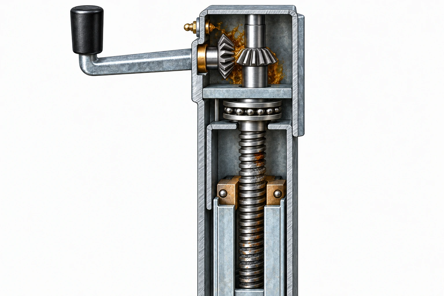
A visible grease fitting can be a useful maintenance feature. However, its presence does not establish that every internal contact surface receives adequate lubrication. Consider a jack with gears near the top of the housing and a screw extending down through the moving leg. Grease introduced near the gear housing may lubricate the gears effectively. Whether it also reaches the thrust bearing, nut and full working length of the screw depends on the actual internal design.
Lubricant does not automatically distribute itself uniformly throughout a mechanism. Component movement, internal passages, grease consistency and the location of the fitting all influence distribution. A 2021 etrailer discussion involving a Fulton jack in rainy Sitka, Alaska [6] illustrates the distinction. The owner reported regularly greasing the top gears through the fitting. Nevertheless, the jack became progressively harder to crank and eventually jammed. After partial disassembly, the owner reported that the upper gears appeared satisfactory while the screw was seized in its nut.
The exchange does not provide an independent engineering examination or establish the root cause with certainty. It does show why visible access to one lubrication point should not be treated as evidence that every internal friction interface is adequately maintained. For jack designers, lubrication access is therefore an engineering feature. For procurement teams, it is a legitimate supplier-qualification question. Where does the lubricant enter, which surfaces does it reach, and how is its distribution verified?
The retailer’s reply also suggested over-extension or over-retraction as a possible explanation. The published exchange therefore does not establish lubrication failure as the cause, and its general troubleshooting suggestions are not a substitute for the product’s approved service instructions. [6]
Maintenance Must Follow the Actual Design
A maintenance instruction suitable for one jack should not automatically be applied to another. Different products may use different grease, oil or dry-lubricant strategies. Some manufacturers provide grease fittings. Others provide removable covers or specific service procedures. Some internal assemblies may not be intended for routine owner disassembly. The Lippert trailer jack maintenance guide [1] distinguishes cleaning, inner-leg lubrication, gear lubrication and protection of the jack head.
The manufacturer also emphasizes following the specific owner's manual. This is important because lubrication can interact with the operating environment. An exposed sliding surface may collect dirt if the lubricant attracts contaminants. An internal screw may require a different lubricant from the external tube. A marine application may place greater demands on resistance to water contamination. Adding lubricant indiscriminately is not a substitute for identifying the correct maintenance requirements.
Nor should a heavily loaded or jammed jack be dismantled without first removing the load and following an approved service procedure. For product design, the relevant question is whether the lubrication system is appropriate for the intended duty cycle and accessible enough to support the expected maintenance strategy. For sourcing, a jack's initial smoothness should be considered alongside its ability to retain acceptable performance after repeated use.
CURT’s maintenance guide similarly treats cleaning, mounting checks and internal screw lubrication as distinct tasks. The model-specific manual governs access and disassembly; unload and safely support the trailer before any approved service work. [7]
Internal Moisture and Corrosion
Trailer jacks operate outdoors. They may encounter rain, road spray, mud, dust and, in marine applications, saltwater. A jack can have a corrosion-resistant exterior while its internal mechanism remains vulnerable to moisture. Water can enter through damaged caps, openings around moving members or other insufficiently protected interfaces. The resulting corrosion may affect the screw, nut, gears or bearings. Corrosion products and contaminants can increase friction.
Lubricant may become contaminated or lose its intended effectiveness. Thread surfaces can develop localized damage. The user may initially notice only a gradual increase in crank effort. Over time, the mechanism may become increasingly difficult to operate. Lippert specifically identifies damaged jack-head caps as a potential route for moisture to reach internal components. CURT also offers a marine jack replacement cap [8] intended to help protect internal parts from dirt, water and rust.
These examples establish the importance of protecting the internal mechanism. They do not mean that an exterior cap alone provides complete environmental sealing. A jack must also accommodate the movement of its telescoping components. Any drainage, ventilation, sealing or lubrication arrangement needs to be compatible with that movement. For marine trailer components, corrosion protection should therefore be evaluated at two levels. The first is the exterior structure.
The second is the internal working mechanism. A corrosion-resistant housing does not automatically make the screw, nut and bearings corrosion-resistant.
Coating, Welding and Installation Complete the Load Path
Finished Clearance After Coating
Surface treatment is necessary for many steel trailer components. However, coating thickness and manufacturing sequence can influence fit. Consider an inner tube and outer tube that have been dimensioned with a defined sliding clearance. If the relevant mating surfaces receive a coating, their final dimensions change. Coating buildup can consume part of the available clearance. For a jack already operating close to its permitted dimensional limits, the change may become significant.
The actual effect depends on the surface-treatment process, which surfaces are coated and the original tolerance allowance. Powder coating, zinc plating and hot-dip galvanizing cannot be treated as dimensionally identical processes. The manufacturer must select a protective system compatible with the component's geometry and intended movement. It may be necessary to define critical dimensions after coating rather than before coating. Some surfaces may require an approved masking or finishing strategy.
Other components may need to be coated separately and assembled afterward. The important point is that surface treatment should not be added to a completed jack design without considering functional clearance. A manufacturer may solve an exterior corrosion problem while inadvertently creating an internal movement problem. The complete design must satisfy both.
Welding Can Change Internal Alignment
A trailer jack's load path does not end at the outer tube. The jack must also connect to the trailer frame. That connection may involve a welded mounting bracket, an A-frame mounting flange or another approved arrangement. Welding introduces localized heating and contraction. If the outer tube or its mounting structure is distorted during fabrication, the jack's internal geometry may be affected. This is especially relevant when the jack body is welded directly to a structural attachment.
Suppose the outer tube is correctly formed and straight before welding. An unbalanced weld around a mounting plate introduces local contraction. The tube develops a small angular or local dimensional deviation. The inner leg may still move freely without load. Once the jack supports the trailer tongue, the unfavorable geometry can increase contact pressure. Operating effort rises. This is a plausible manufacturing failure chain: Accurate tube → welding heat → local distortion → reduced alignment margin → loaded contact → increased friction.
It is not evidence that all welded trailer jacks suffer this problem. A correctly designed and controlled welding process can produce acceptable geometry. The lesson is that the final jack must be evaluated after the manufacturing operations capable of changing its dimensions. The previous Materials & Manufacturing article established the broader principle: precision cutting does not guarantee precision after welding. A trailer jack makes that principle tangible because small geometric errors can become noticeable as operating resistance.
Vertical Capacity Does Not Authorize Arbitrary Side Loading
Trailer jacks primarily raise and support the trailer tongue through an intended load path. The real installation may introduce additional forces. An uneven surface can change how the foot or wheel contacts the ground. An off-center mounting arrangement can introduce a bending moment. Moving a wheeled jack across rough ground can create lateral forces. A trailer can also move unexpectedly if it is not properly secured.
These loading conditions are not interchangeable with a controlled vertical capacity test. A jack designed for vertical lifting should not be assumed to tolerate any lateral load simply because its advertised lifting capacity is large. Similarly, two jacks with the same vertical rating may respond differently to permissible off-center loading because of differences in tube geometry, guide overlap, mounting structure and internal alignment. The manufacturer should define the intended installation and operating conditions.
The OEM should select the jack accordingly. The buyer should not interpret a 5,000 lb vertical rating as permission to use the jack for arbitrary side loading, trailer moving or lifting operations outside its instructions. For evaluation purposes, vertical capacity testing and an application-specific off-center loading assessment answer different questions. Both may be relevant to a particular product, but one does not automatically replace the other.
Test How the Jack Operates, Not Only What It Lifts
Capacity, Operation and Durability Are Different Tests
Suppose a jack successfully raises its rated load during a factory test. That is valuable evidence. It confirms that the tested unit performed a specified lifting operation under the conditions used. It does not establish that the mechanism will maintain the same operating effort after years of use. The screw and nut experience repeated sliding contact. Gears transmit torque through repeated tooth engagement. Bearings support the load during rotation.
Telescoping surfaces move against their guides. Lubricant must continue functioning. The mechanism may also experience outdoor contamination and corrosion. A single successful lifting operation cannot evaluate all of those effects. A static holding test answers a different question again. It can assess whether the jack supports a specified load under defined conditions. It does not establish how smoothly the mechanism will raise that load. A useful qualification program should distinguish between capacity, operating performance and durability.
The ability to lift a load once is not the same property as the ability to lift it smoothly and repeatedly throughout a specified service life.
Measurements Across the Permitted Stroke
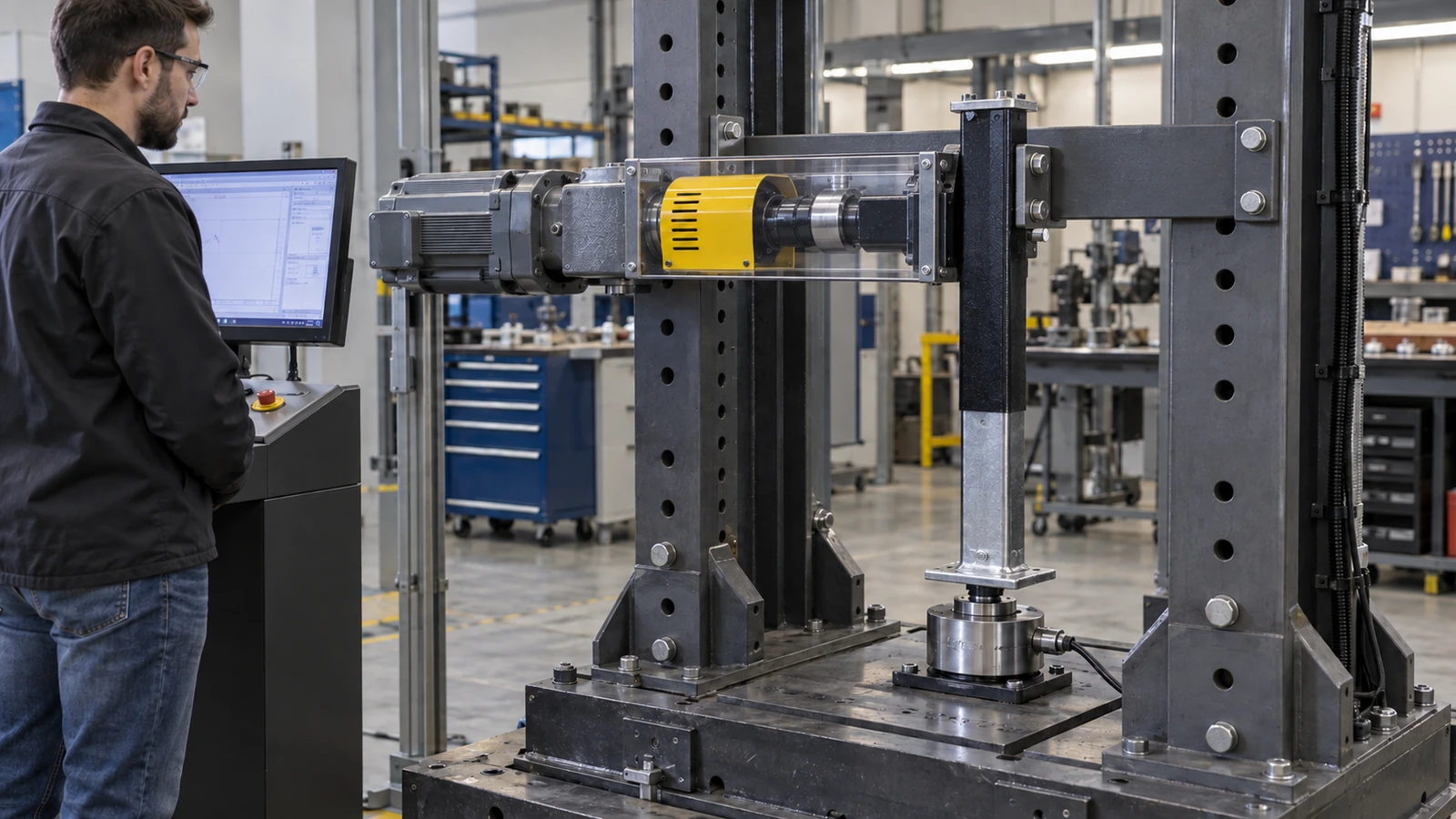
A useful jack qualification program begins with the product's intended function. The OEM should establish the applicable lifting load, support requirement, travel range and operating conditions. The test can then examine whether the completed jack performs consistently across those conditions. For a manual screw jack, several measurements may be useful. Unloaded operating torque helps identify abnormal mechanical resistance before the rated lifting load is applied.
Loaded operating torque shows the input required to raise the specified load. Torque variation throughout the stroke can reveal whether resistance increases at particular positions. Travel per handle revolution helps characterize operating speed and the mechanical arrangement. Post-cycle operating torque can show whether performance changes after repeated operation. Final dimensional and functional inspection can identify wear, permanent deformation, excessive play or other changes. These are proposed engineering measurements, not a claim that every trailer jack is required by a universal standard to pass one identical test.
The OEM must define appropriate test loads, operating speeds, stroke positions, cycle counts, tolerances and acceptance criteria for its application. A meaningful test should also distinguish between normal resistance near a designed travel stop and unintended binding within the permitted operating range. The manufacturer should never force a jack beyond its designed travel to obtain an additional measurement. For products intended for powered operation, the test should follow the approved input-drive and torque limitations.
The objective is to characterize the actual mechanism without creating an unsafe test condition.
What a Torque-versus-Travel Curve Can Reveal
Consider an illustrative comparison between two jacks with the same lifting rating. Both are tested using the same load, handle arrangement and measurement procedure. Jack A operates with relatively consistent torque throughout its permitted travel. Jack B operates smoothly during the first portion of the stroke but develops a pronounced increase in torque near the end. Both may still complete the lifting operation. A simple pass/fail capacity test could record both as successful.
A torque-versus-travel measurement would reveal an important difference. The curve does not automatically identify the root cause. The increase could involve alignment, local tube interference, screw condition, bearing behavior or another mechanism. Further inspection would be necessary. But the measurement provides a much more informative basis for investigation. It also allows the manufacturer to compare production batches. If a previously stable process begins producing jacks with increasing torque variation, the change may indicate a manufacturing or assembly issue that deserves attention.
An OEM should avoid specifying an arbitrary universal crank-torque limit without considering the design. A faster screw or different gear ratio can change the required input torque while still delivering acceptable performance. Handle length changes the hand force required for a given torque; it does not, by itself, change the mechanism’s torque requirement. The useful comparison is against the product's defined operating requirement. A load rating tells the buyer what the jack is required to carry or lift. A torque curve helps explain how it performs that operation.
From a Good Prototype to Repeatable Production
Process Capability Beyond the Prototype
A carefully assembled prototype can perform exceptionally well. Its tubes may be selected for fit. Its screw and nut may be aligned by an experienced technician. Its gears may be adjusted carefully. Its lubrication may be applied thoroughly. The challenge is reproducing that condition at production scale. When thousands of components enter the assembly process, small variations become important. Tube dimensions vary within manufacturing tolerances.
Forming and straightening processes introduce variation. Screw geometry and surface finish can differ between batches. Nut positioning may change. Gear mounting dimensions can vary. Welding fixtures wear. Lubrication quantity and distribution can become inconsistent. Coating buildup may differ between components. Every variable may appear relatively small on its own. Together, they influence the finished mechanism. This is where supplier process capability matters. A manufacturer should understand which characteristics are critical to jack function and establish appropriate controls.
For example, an OEM may require verification of telescoping clearance, screw alignment, operating torque and final travel. The manufacturer may use gauges, dimensional inspection, functional tests and process monitoring to demonstrate that these requirements are maintained. The exact methods depend on production volume and component design. Not every jack needs to undergo an expensive laboratory endurance test. However, an effective quality plan should connect incoming component control, process validation, routine inspection and periodic performance verification.
The objective is not merely to manufacture a jack that can pass qualification. It is to establish a process that repeatedly manufactures acceptable jacks.
Final Functional Verification
Component inspection remains important. An incorrectly manufactured screw should not enter assembly. A bent tube should not be accepted merely because a completed jack might still operate. But final assembly introduces interactions that individual inspection cannot fully predict. Two acceptable tubes may have an unfavorable clearance combination. A correctly manufactured nut may be installed with an angular deviation. A suitable bearing may be seated incorrectly.
A gear set may be assembled with excessive or insufficient engagement. A properly formed outer tube may be distorted during mounting-bracket welding. These problems can appear only after the components interact. The completed jack therefore needs appropriate functional verification. For a production-critical application, that may include checking travel, operating resistance and any relevant locking or retention functions. The test should be performed in a defined condition.
A lightly loaded factory test and a rated-load qualification test do not provide the same evidence. The OEM should establish which tests are required for every production unit and which are appropriate for sampled qualification or periodic validation. This distinction allows inspection effort to remain proportional to product risk. The goal is not to test everything in every possible way. It is to prevent critical assembly problems from escaping simply because all the incoming parts individually passed inspection.
What to Put in the RFQ
A conventional jack RFQ often contains basic specifications: Rated capacity, travel, tube size, mounting style, handle type and surface treatment. Those requirements are necessary. They are not always sufficient to distinguish manufacturing performance. For a jack intended for frequent use or a demanding service environment, procurement should consider the following additional requirements.
| Specification area | What the buyer should clarify |
|---|---|
| Capacity | Lifting capacity, static support capacity and applicable rating conditions |
| Application | Intended installation, actual tongue load and permitted operating conditions |
| Travel | Screw travel, total height adjustment and applicable stroke limits |
| Operation | Acceptable input effort, travel speed and relevant operating positions |
| Tube geometry | Straightness, cross-sectional dimensions and finished telescoping clearance |
| Screw and nut | Appropriate thread geometry, material, alignment and manufacturing controls |
| Gearing | Intended gear ratio, operating characteristics and assembly requirements |
| Bearing system | Suitability for axial loading, alignment and lubrication |
| Welding | Mounting geometry, distortion control and inspection requirements |
| Lubrication | Factory lubrication, maintenance access and approved lubricant |
| Corrosion protection | Exterior coating, internal protection and environmental exposure |
| Functional testing | Required unloaded, loaded and full-stroke verification |
| Durability | Agreed cycle-test conditions and post-test acceptance requirements |
| Batch consistency | Traceability, process controls and production verification |
Not every item requires a separate numerical tolerance on every drawing. The specification should identify the characteristics that materially affect the intended product. For example, a high-volume OEM might define an operating-torque acceptance range under a controlled test load. Another application might place greater emphasis on environmental protection and maintenance accessibility. The important improvement is to move beyond capacity as the sole purchasing criterion. A supplier should understand what successful operation means, not merely what number must appear on the label.
Read the Conditions Behind Cycle Claims
A supplier may advertise that a jack has passed thousands of operating cycles. That statement can be useful. It is incomplete unless the test conditions are known. Was the jack tested without a load? Was it lifting a specified load? Did each cycle use the complete permitted travel? Was the mechanism exposed to moisture or contaminants? Was additional lubrication allowed during the test? What counted as failure?
A jack might complete the required number of cycles but develop substantially higher operating torque. Another might retain smooth movement but show excessive play or wear. A third might experience a structural problem. The appropriate acceptance criteria depend on the intended application. A meaningful durability requirement may therefore evaluate more than whether the jack continues moving. It may include post-test operating effort, functional clearance, visible wear, structural condition and retention of the required capacity.
The OEM should also distinguish between accelerated cycling and actual service-life prediction. A controlled endurance test can provide comparative or qualification evidence. It does not automatically establish a fixed number of years outdoors. A marine jack exposed to saltwater may deteriorate differently from an identical mechanism tested in a clean laboratory. Testing must follow the failure mechanism the buyer intends to control.
Buy a Repeatable Lifting Function
Total Cost Beyond Purchase Price
Two 3,500 lb jacks may appear commercially interchangeable. Their mounting arrangements may be similar. Their advertised travel may be comparable. Their initial purchase prices may differ. However, the total cost of ownership can also include operating effort, maintenance, replacement frequency, installation labor and warranty handling. A jack that becomes difficult to operate may create additional service work. A prematurely corroded screw may require replacement of the complete assembly if the internal mechanism is not economically repairable.
A jack with inconsistent mounting geometry may require additional fitting during trailer production. For an OEM producing large numbers of trailers, small assembly problems can accumulate into meaningful manufacturing costs. The lowest quoted jack price does not necessarily produce the lowest finished-trailer cost. Conversely, a more complex internal mechanism is not automatically worth purchasing if the application does not require its additional features. The appropriate sourcing decision depends on the actual duty cycle and service requirements.
The objective is to obtain the required performance consistently and economically. The purchasing unit is not simply a jack with a specified load rating. It is a repeatably manufactured lifting function.
GOODIN View
A trailer jack is a relatively compact mechanical assembly. Its performance depends on much more than the strength of its outer tube or the size of its screw. Tube straightness influences guidance. Clearance affects sliding behavior. Screw and nut geometry determine load transfer and friction. Gearing influences operating effort and travel speed. Bearings support axial load while allowing rotation. Welding can change alignment. Surface treatment can affect clearances.
Lubrication and environmental protection influence how the mechanism behaves over time. And manufacturing variation determines whether those properties remain consistent across production batches. A load rating does not describe all of these characteristics. It establishes a capacity requirement under the applicable definition and rating conditions. Two products can satisfy that requirement while delivering different operating experiences. The difference may be most visible when a user encounters binding near full extension, increasing crank resistance or premature internal wear.
But the underlying causes can originate much earlier. They may begin with tube forming, screw manufacture, nut positioning, welding, coating or assembly. This is why GOODIN's view of trailer component quality should extend beyond the nominal specification. For OEMs, the jack should be evaluated as a complete operating mechanism. For procurement teams, the RFQ should define relevant performance requirements in addition to capacity. For manufacturers, dimensional control, process capability and functional testing should be part of the production system.
GOODIN View: A load rating defines a capacity threshold. It does not define manufacturing quality. The deeper principle is equally important: Nominal specifications tell the buyer what a product is designed to do. Process capability determines how consistently production units can actually do it. A better trailer jack is not established by a larger capacity label, an attractive finish or an impressive-looking internal component alone.
It is established by the complete design and the manufacturer's ability to reproduce its intended performance. That is the difference between selling a rated component and engineering a dependable product. For OEM selection, explore GOODIN trailer jacks and discuss your required loaded effort, travel and batch acceptance plan with GOODIN.
Sources & Further Reading
Technical context, not a universal acceptance standard or service procedure. Follow the specific product manual. Owner reports describe symptoms, not independently confirmed causes; a patent describes a design, not comparative durability evidence.
- Lippert — The Ultimate Guide to Trailer Jack Replacement
- BULLDOG — Model 182524 — Heavy-Duty Square Trailer Jack
- Douglas Wright / Cambridge-hosted DANotes — Screw Jack Mechanics Example
- etrailer — 2,000 lb Jacks With Different Cranking Speeds
- etrailer — Trailer Valet JXS Binding Near the Top of the Lift (2025)
- etrailer — Fulton Jack Seizure and Internal Lubrication (2021)
- CURT — A Comprehensive Guide to Trailer Maintenance
- CURT — Replacement Marine Jack Cap — 28925
- Atwood / B. Douglass — US3851855A — Thrust Ball Bearing Construction for Trailer Jack
Robotic Welding Is Moving Into High-Mix Trailer Production: But Can Automation Handle Real Part Variation?
A Perfect Cut Can Still Produce a Crooked Trailer: How Welding Sequence and Heat Distortion Destroy Dimensional Accuracy
Related Article