Robotic Welding Is Moving Into High-Mix Trailer Production: But Can Automation Handle Real Part Variation?
On this page
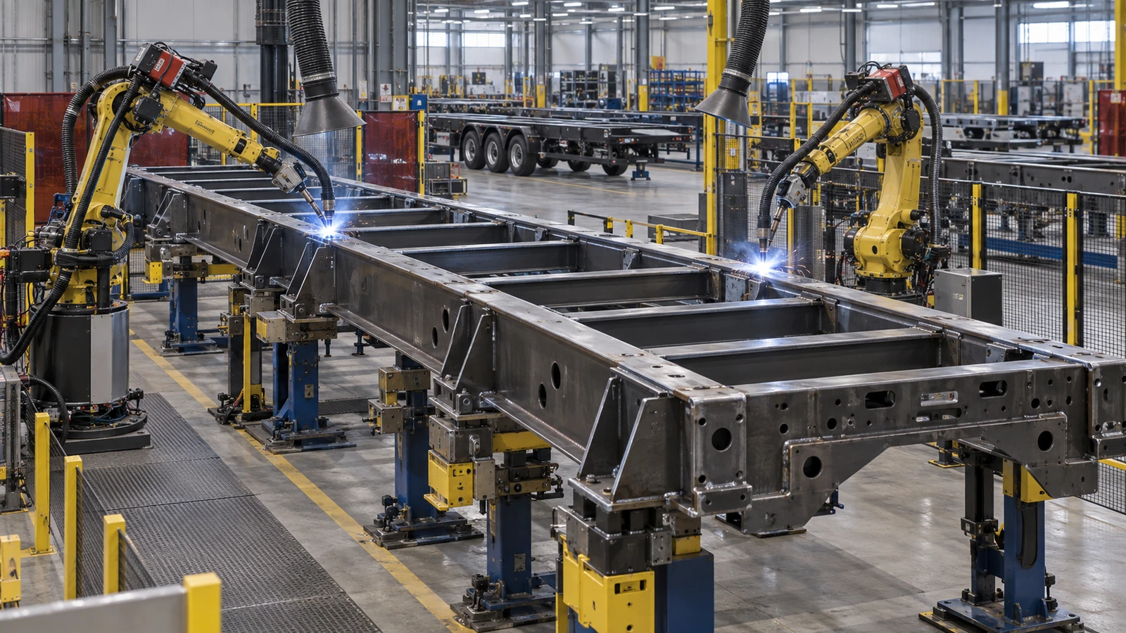
A welding robot can repeat the same programmed movement thousands of times. It can follow a defined path, maintain a controlled travel speed and reproduce a specified torch angle with remarkable consistency. But what happens when the next trailer frame is not exactly where the robot expects it to be? A cross-member may be slightly out of position. A formed bracket may have a different springback angle. A hollow steel tube may arrive with a dimensional variation. The joint gap may be wider than the one used to create the original welding program.
An experienced welder can see many of these differences and adjust their work accordingly. A robot following a fixed program does not automatically know that the parts have changed. This is the central engineering challenge as robotic welding moves beyond long production runs of identical components and into high-mix, low-volume trailer manufacturing. The objective is no longer simply to repeat a weld accurately. It is to produce an acceptable weld when the actual component differs from the ideal geometry in the digital model.
That distinction changes how trailer manufacturers should evaluate automation, fixtures, welding procedures, inspection and supplier capability. It also explains why the next stage of manufacturing automation is not necessarily about eliminating variation. It is about identifying and managing variation before it becomes a defect.
Engineering feature · Materials & Manufacturing
Why High-Mix Trailer Production Is Entering the Automation Debate
For years, the most straightforward applications for robotic welding have involved parts that remain geometrically consistent across large production runs. The economic logic is clear. A manufacturer invests time in developing the welding program, building fixtures and validating the process. Once those tasks are complete, the same setup can produce many identical assemblies. High-mix, low-volume manufacturing changes that calculation. A trailer manufacturer may produce several chassis lengths, axle configurations and mounting arrangements. Customers may specify different brackets, cross-members or reinforcement details. A production batch may contain only a few examples of one design before the next variant arrives.
The welding work remains substantial, but the manufacturer cannot necessarily spread programming and fixture costs across thousands of identical units. The National Association of Trailer Manufacturers identified this challenge in its planning for the 2026 Convention & Trade Show. Its announcement described a Technical Forum scheduled for February 24, 2026, Driving Efficiency in Trailer Manufacturing – The Case for Automation, covering how manufacturers of different sizes could evaluate automation in welding, bending, riveting and assembly.
The forum announcement specifically included custom-shop environments and emphasized identifying real production bottlenecks rather than assuming that every factory needs the same automation solution. [1]
What the Tyllis Announcement Actually Establishes
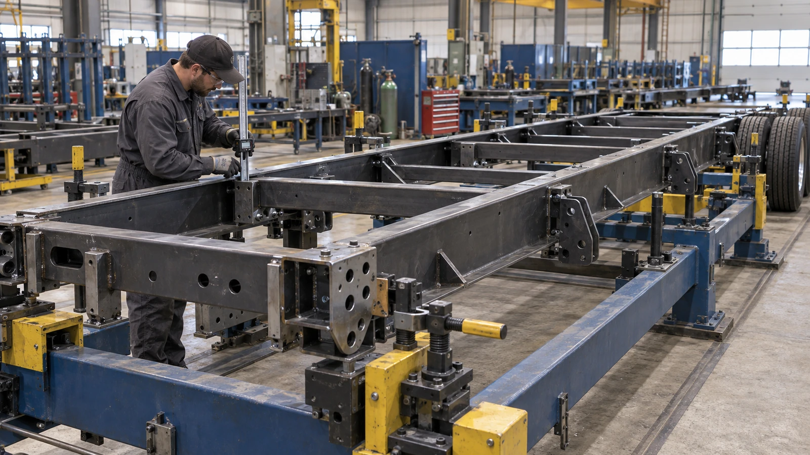
A more concrete development followed on May 7, 2026. Valk Welding reported the fully automatic generation of a welding program for a complete trailer chassis at Finnish manufacturer Tyllis Oy Ab, using Automatic Robot Programming technology developed with ArcNC. Tyllis manufactures customized transport equipment, including trailers, dollies, crane trucks and semitrailers. The project involved a large, complex chassis and a modular welding fixture designed to accommodate different products.
Valk Welding presented the successful programming of the complete chassis as evidence that automatic programming can support even very small production batches. [2] This is an important development, but its meaning should be kept precise. The published announcement reports completed automatic program generation and identifies its accompanying chassis image as a factory acceptance test. It does not publish a formal acceptance report or establish that every future chassis variation can be welded without human intervention, that all fit-up problems are automatically corrected or that manual inspection has become unnecessary.
The distinction matters because generating a welding path and executing an acceptable weld on a variable physical assembly are different engineering tasks. Automatic programming helps the robot understand what the design requires. Adaptive welding helps it respond to what the factory actually produces. Both capabilities are relevant to the next generation of trailer manufacturing.
A Correct CAD Path Can Miss the Real Joint
When the Physical Bracket Differs from the Model
Offline robot programming begins with a digital representation of the intended workpiece. The software can use geometry from CAD data to establish weld locations, generate torch paths and evaluate accessibility. It can also simulate robot movement and identify potential collisions within the modeled production cell. That is valuable for custom trailer manufacturing. Instead of manually teaching every weld on every new chassis, a manufacturer can generate or reuse parts of the welding program from the digital design.
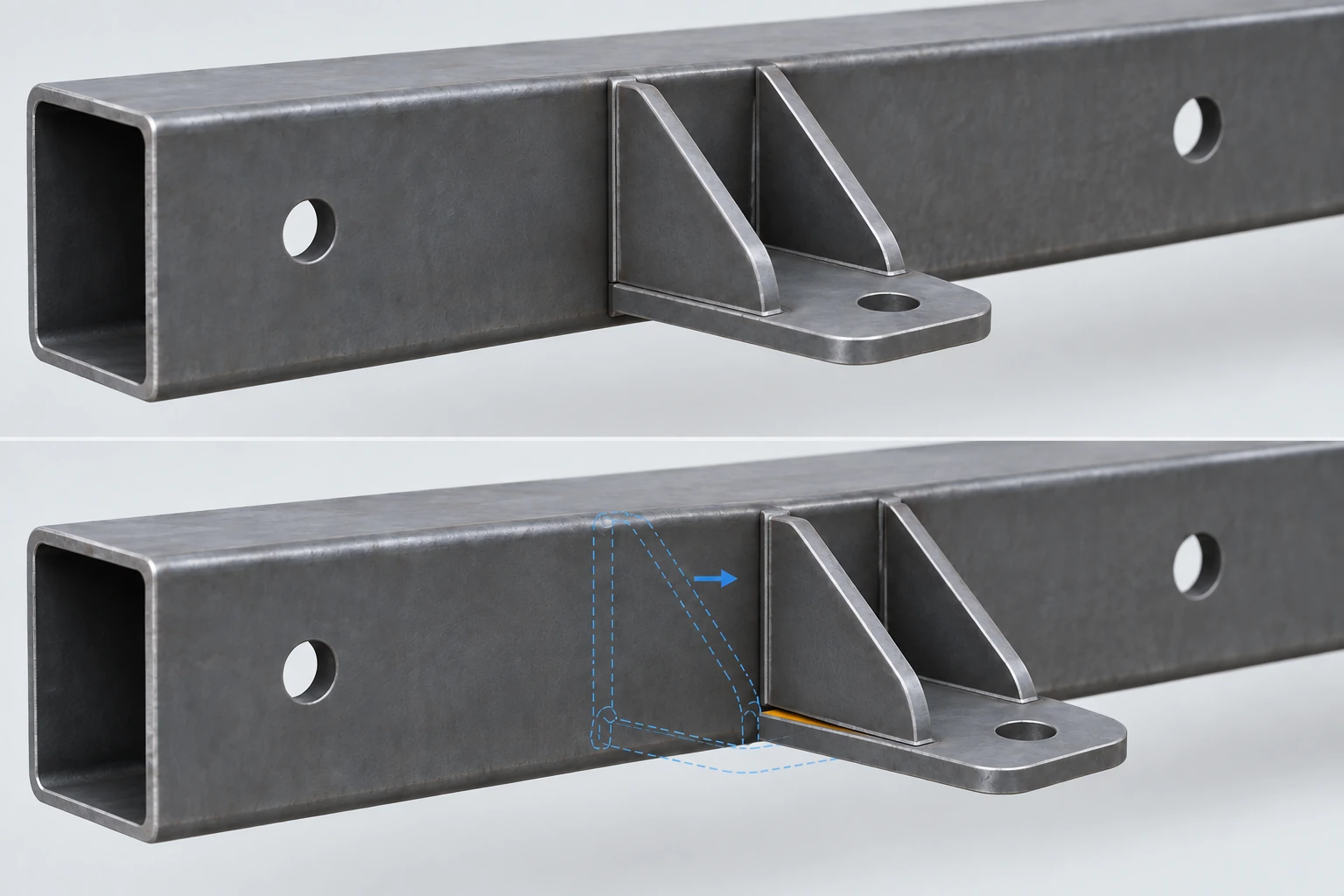
However, the digital model describes intended geometry. The physical fabrication has tolerances. A steel tube may be slightly bowed. A formed plate may have more springback than expected. A tack-welded cross-member may have moved. The fixture may introduce a small positioning error. The programmed weld location and the actual joint can therefore differ. Consider a robotic cell programmed to weld a suspension bracket onto a rectangular chassis member.
The software identifies the intended fillet weld location in the CAD model. The robot approaches the programmed position. But the real bracket is slightly displaced because its formed angle differs from the nominal design. If the robot follows its original path without compensation, the torch may no longer maintain the intended relationship to both members of the joint. The weld can become asymmetrical. Depending on the deviation and welding process, it may also suffer from inadequate fusion, poor bead placement or other defects.
The robot has not necessarily lost its positional accuracy. It may be following the programmed path correctly. The failure occurs because the physical joint does not match the geometry used to create that path. This is why CAD-to-robot programming and real-part verification must be considered together.
Repeatability Is Not Finished-Product Accuracy
Industrial robots are frequently marketed using repeatability specifications. Repeatability describes how consistently a robot can return to a commanded position under defined conditions. It is an important machine characteristic. But it does not establish the accuracy of the entire welding process. The robot's coordinate system must be correctly related to the fixture and workpiece. The tool center point must be calibrated. The welding torch and contact tip must remain in the intended condition.
The workpiece must be positioned sufficiently consistently, or its actual position must be detected. The joint must also remain within the conditions for which the welding procedure was developed. These requirements form a chain: Robot calibration → fixture reference → actual part position → joint geometry → torch path → welding process → finished assembly. A highly repeatable robot can reproduce an incorrect path with excellent consistency.
If a bracket is displaced by a manufacturing error, repeating the nominal program does not eliminate that displacement. Similarly, accurate robot movement does not prevent the welded assembly from distorting during cooling. The previous Materials & Manufacturing article established that accurate laser cutting cannot guarantee accurate finished geometry. Robotic welding extends the same principle. Robot positioning accuracy is an input to manufacturing precision, not proof of finished-product quality.
For procurement teams, the useful evidence is therefore not simply the robot's published repeatability specification. It is the demonstrated quality and dimensional consistency of the actual welded component.
Small Tolerances Can Create a Large Fit-Up Problem
High-mix trailer production introduces several sources of variation before a part reaches the welding station. Laser-cut components may vary within their permitted dimensional tolerances. Formed components may have different springback responses. Long steel sections may have small straightness deviations. Material thickness may vary. A manually prepared assembly may contain inconsistent tack-weld positions. Fixture loading may differ between operators or product variants. These deviations may be acceptable individually.
But they interact during assembly. Suppose a cross-member is slightly shorter than nominal. The chassis rails are also slightly farther apart than nominal. The resulting joint gap becomes larger than intended. A manual welder may recognize the gap and adjust within the limits of the approved welding procedure. A robot following a fixed program may continue depositing the same weld at the same location. The result depends on the actual gap and the process being used.
A modest deviation may remain acceptable. A larger gap can change the required weld volume, penetration conditions and resulting distortion. If the joint falls outside the qualified process range, simply modifying travel speed or increasing filler deposition is not necessarily an acceptable correction. The problem may require a fit-up adjustment or rejection of the assembly. This is the central manufacturing distinction: Variation that can be detected is not necessarily variation that can be safely compensated for.
A capable automated system needs to recognize the difference.
Fixtures, Seam Finding and Tracking Do Different Jobs
Adapting to the Part Is Not Correcting the Part
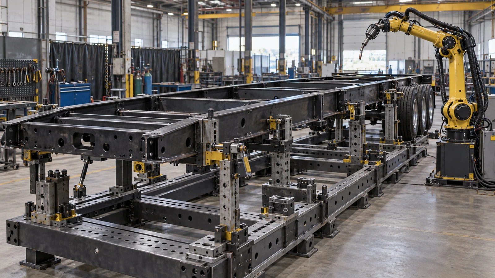
Adaptive welding technology can reduce dependence on extremely rigid part positioning. It does not eliminate the need for fixtures. A fixture establishes the structural relationship between the components being welded. It holds the parts in an intended arrangement while welding forces, thermal expansion and shrinkage develop. For a trailer frame, the fixture may need to control longitudinal beam spacing, cross-member position, mounting features and overall assembly geometry.
A robot sensor can sometimes detect that a joint has moved. It cannot automatically correct every structural consequence of that movement. Consider a chassis rail that is positioned incorrectly in the fixture. The robot detects the actual weld location and adjusts its path. It then produces a sound weld between the rail and cross-member. The joint may be acceptable. But the finished frame may still have incorrect geometry.
The robot successfully adapted to the part. It did not correct the part. This is a critical limitation. Adaptive path correction can help produce a weld at the actual joint. It does not automatically establish that the joint is in the correct location within the trailer. The fixture must still control the dimensions that determine finished-product function. A well-designed automation strategy therefore uses fixtures and sensing for different purposes.
Fixtures establish the required assembly geometry. Sensors identify permitted deviations from the expected welding position. The robot adapts within validated limits. Inspection verifies the resulting joint and finished assembly. Removing the fixture entirely may be possible for some applications, but it should not be treated as the inevitable objective of automation. The appropriate level of fixturing depends on part geometry, structural requirements, manufacturing variation and production economics.
Locate the Joint Before Welding
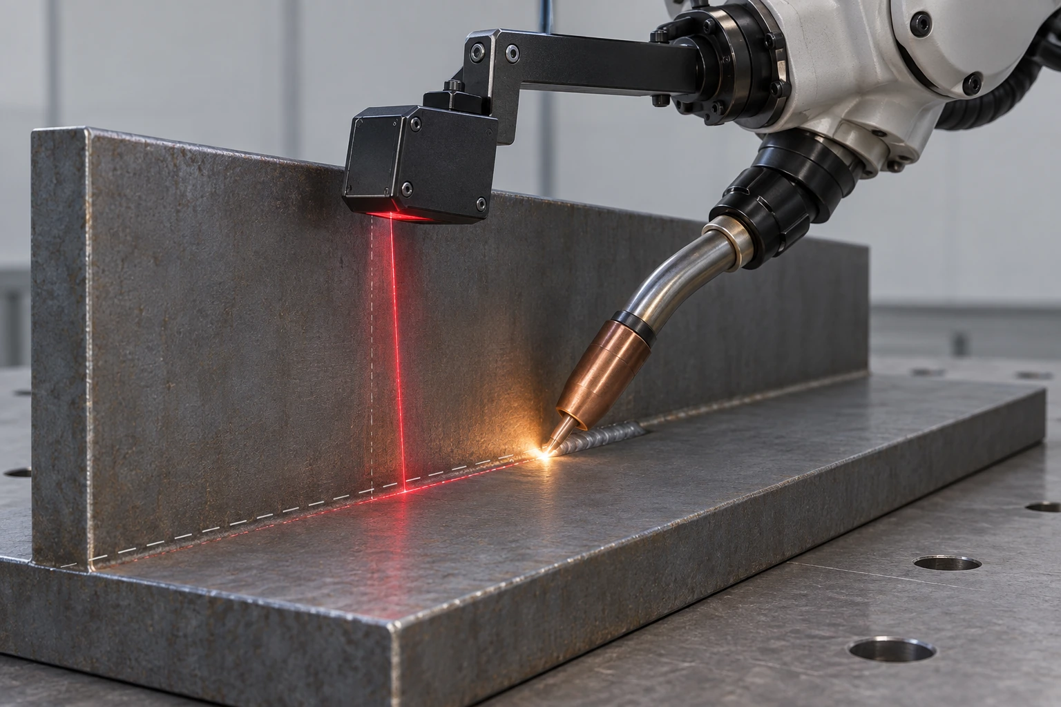
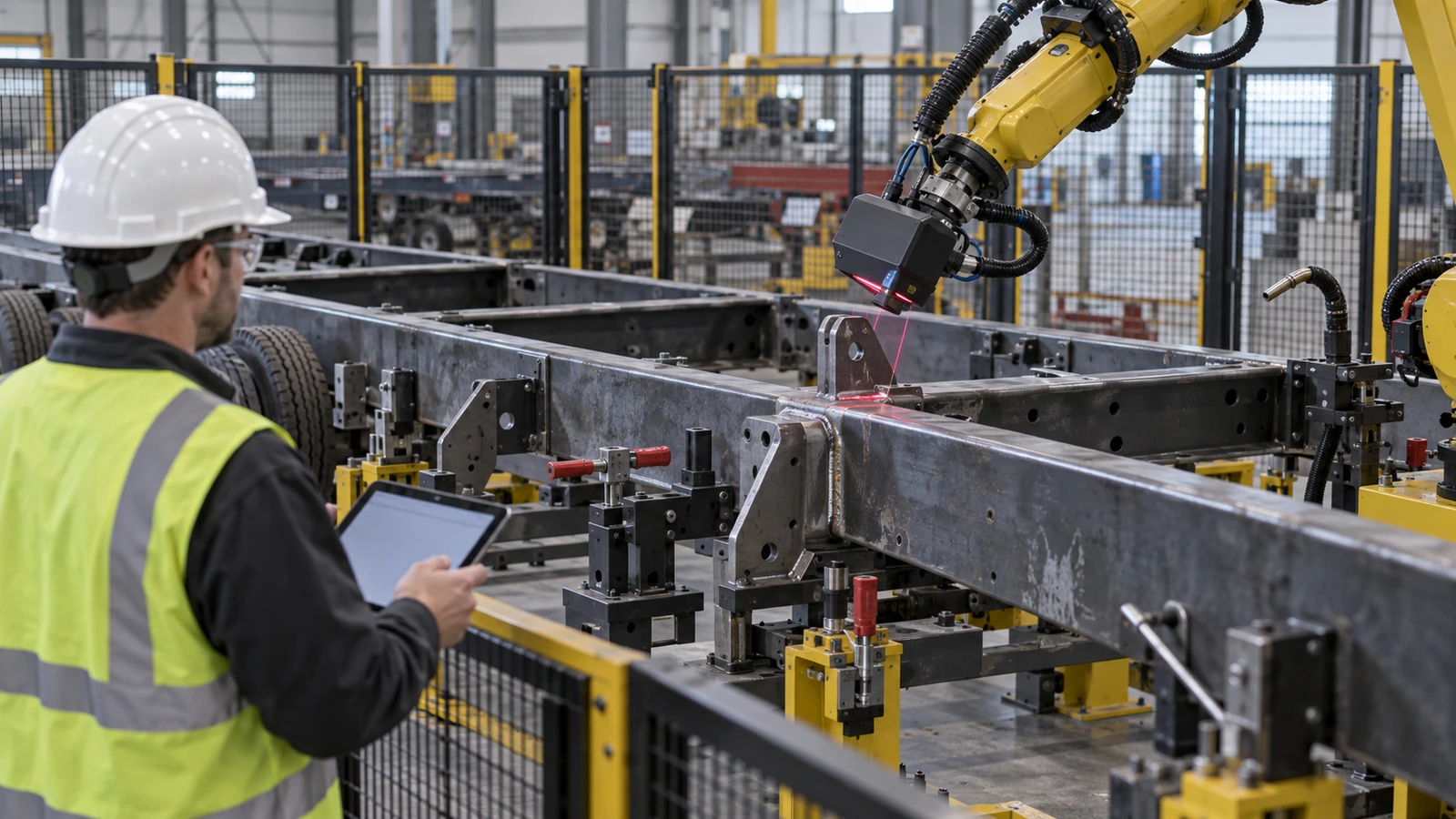
One approach to handling part variation is to detect the actual joint before welding begins. This is generally described as seam finding or touch sensing. A robotic system may use a welding wire, gas nozzle, contact probe, laser sensor or another suitable sensing method to identify relevant features of the workpiece. The robot uses those measurements to correct the intended weld path. For example, a sensor may identify the actual start and end positions of a fillet weld.
The controller can then adjust the programmed path to account for a small displacement in the component. Fronius describes this approach in its robotic welding assistance systems [4]. Its TouchSense technology uses the welding wire or gas nozzle to locate the workpiece before welding, allowing the robot to compensate for certain positioning and clamping tolerances. The manufacturing value is straightforward. The robot no longer relies entirely on the assumption that every part occupies the identical nominal position.
However, seam finding has a defined purpose. It establishes or corrects joint location. It does not automatically establish that the joint gap is acceptable, that the underlying material is correct or that the assembly satisfies its structural dimensions. A detected weld location can still be associated with an unacceptable fabrication. The sensing system therefore needs appropriate acceptance limits. If the detected deviation exceeds the permitted range, the correct response may be to stop and request inspection rather than continue welding.
Fronius's SAG application also illustrates wire-based detection of an actual joint before welding. WireSense uses the wire as a sensor; this should not be confused with continuous in-arc seam tracking. [5]
Follow the Joint During Welding
Finding the joint before welding is not the same as following it during welding. A long trailer frame can experience additional movement as the welding process progresses. Heat changes the shape of the assembly. [10] The joint may move relative to the programmed path. A sensor that measured only the initial position may not detect all subsequent changes. Seam tracking addresses this problem. Depending on the technology, the system may use arc signals or optical sensing to estimate how the joint position changes during welding.
The robot can then adjust its path within the system's permitted range. Fronius distinguishes between its TouchSense and SeamTracking functions. TouchSense locates the joint before welding. SeamTracking provides corrections during the welding operation. [4] The company specifically identifies compensation for component and clamping tolerances as an application of these technologies. This distinction matters for long trailer structures. A frame may be correctly positioned at the start of a weld but develop local movement during the operation.
An adaptive system may be able to follow that movement. However, tracking the joint does not automatically prevent the overall frame from distorting. The robot may produce a weld that follows the changing geometry accurately. The completed chassis may still require dimensional verification after cooling and fixture release. Seam tracking controls the relationship between the torch and the joint. It is not a substitute for controlling the geometry of the entire welded structure.
Adaptation Needs a Qualified Operating Window
Vision Must Work in the Real Cell
Vision-based welding is often described as though adding a camera gives the robot the same judgment as an experienced welder. The reality is more complicated. A vision system must acquire usable information from the actual manufacturing environment. Trailer fabrication introduces several challenges. Steel surfaces can be reflective. Welded assemblies contain shadows and occluded corners. Spatter, smoke and fumes can interfere with optical measurements. The welding arc creates an intense light source.
Large frames may contain joints that are difficult for a sensor to approach. Surface condition and component geometry may change between product variants. The sensor must also distinguish the intended joint from nearby edges, previous welds or other features. These are not reasons to reject vision technology. They are requirements that should be evaluated during system integration. A sensor suitable for locating an open fillet weld may not perform equally well inside a deep bracket recess.
A system developed around clean laboratory specimens may require additional protection, calibration or data processing in an industrial welding cell. The relevant question is not simply whether the robot has a camera. It is whether the sensing system can reliably identify the required features under the actual lighting, surface, access and welding conditions. A September 2026 article published by the American Welding Society and written by Universal Robots executive Anders Billesø Beck, Physical AI Enables Adaptive Welding Automation [6], discusses the increasing importance of perception and adaptation in manufacturing environments with variable fit-up and changing part locations.
It also recognizes that fully end-to-end AI systems remain difficult to validate over long periods. For trailer manufacturers, this suggests a practical approach: use sensing to solve clearly defined manufacturing problems, and establish where the system's reliable operating limits end.
Not Every Gap Can Be Compensated For
Gap variation is one of the most important limitations of adaptive robotic welding. Suppose a robotic system detects that a joint gap is larger than expected. The robot may be capable of adjusting its position. Some welding systems can also adapt selected welding parameters or deposition strategies. But the system cannot assume that every gap can be corrected by adding more weld metal. The acceptable gap depends on the joint design, material thickness, welding process and qualified procedure.
A larger gap may require additional filler metal. It may affect penetration, weld geometry or the risk of burn-through. It can also change heat input and the resulting distortion. For a thin trailer component, an attempt to bridge an excessive gap may create an unacceptable weld. For a thicker structural connection, the appropriate response may be a different qualified welding arrangement. The robot needs a decision boundary.
If the gap falls within a validated range, the system may apply an approved correction. If the gap exceeds that range, the part should be corrected, rejected or referred for engineering review. This distinction is especially important in high-mix production because different trailer variants may use different thicknesses and joint configurations. A parameter adjustment qualified for one joint should not automatically be transferred to another.
Adaptive welding should reduce the consequences of acceptable variation. It should not normalize unacceptable fit-up.
Consistent Execution Can Also Repeat Defects
Robotic welding can improve consistency when the process is correctly designed and controlled. The opposite is also possible. If the programmed torch angle is wrong, the robot can repeat that angle across an entire batch. If the contact tip is damaged, the programmed path may no longer produce the intended wire position. If shielding gas delivery is inadequate, a consistent robot path does not prevent porosity.
If incoming components are contaminated, automation does not remove the contamination. If the welding parameters are unsuitable for the joint, repeatable execution does not make them acceptable. The robot can therefore produce highly consistent defects. This is why manufacturing repeatability and welding quality must be distinguished. Repeatability describes how consistently an operation is performed. Quality describes whether the resulting operation satisfies the required specification. A capable robotic process needs both.
The manufacturer must establish the correct weld design and welding procedure before relying on repeatability. The production system must then maintain the relevant conditions, including material preparation, fit-up, equipment condition, shielding, welding parameters and inspection. The welding program is only one part of that system.
Keep Parameter Changes Inside the Qualified Process
One attraction of robotic welding is the ability to reproduce programmed parameters. The system can maintain a defined travel speed, wire-feed setting and welding sequence more consistently than an uncontrolled manual process. That capability can be valuable for trailer components requiring repeatable weld geometry. However, consistency is only useful when the parameters are appropriate for the actual joint. A programmed procedure developed for one material thickness may not be suitable for another.
A different joint gap can change the amount of filler required. A change in welding position can alter the behavior of the molten weld pool. A different filler metal or shielding-gas arrangement may require another approved setup. Automated parameter changes therefore need to remain within a validated process window. The published scope of the 2026 edition of AWS B2.1/B2.1M [8] addresses qualification of welding procedures and welding personnel across manual, mechanized and automatic processes.
The applicable structural code, contract and product requirements determine which qualifications are necessary for a particular trailer application. The broader principle is that automation does not remove the need to establish and qualify the welding process. It changes how that qualified process is executed and controlled. A robot capable of adjusting parameters should not be given unlimited authority to compensate for poor incoming material or unacceptable assembly conditions.
For a trailer OEM, the relevant requirement is a controlled relationship between the detected joint condition and the permitted welding response.
Programming and Modular Fixtures Change the Economics
Reuse Engineering Knowledge Through Welding Templates
Traditional robotic welding often relies on a substantial initial programming investment. A programmer develops the path, adjusts torch orientation, checks accessibility and validates the sequence. That work can be economical when thousands of identical components follow. The economics change when a trailer manufacturer produces only a few examples of each configuration. Suppose a factory builds three chassis variants in a week. Each variant requires different bracket positions, cross-member arrangements and weld lengths.
If the robot must be manually reprogrammed for every change, programming time can become a significant portion of the total production effort. The welding robot may spend less time depositing weld metal than the factory spends preparing it for the next product. This is why automatic programming and reusable welding templates are relevant to high-mix manufacturing. A manufacturer can develop standard welding strategies for recurring joint families.
The software can then apply those strategies to suitable features identified in the digital model. A fillet weld between two standard structural members may reuse a validated programming approach even when its location changes between trailer variants. A more complex attachment may require additional engineering review. The goal is to reduce unnecessary programming effort without assuming that every geometrically similar weld is technically interchangeable. The April 2026 Visual Components discussion of advanced offline welding programming [7] describes this approach through reusable weld templates, welding databases and automatic path optimization.
The manufacturing significance is that programming becomes more closely integrated with engineering data. However, the physical assembly must still be verified. A reusable digital program can reduce changeover time. It cannot guarantee that the next physical chassis matches the model.
The Tyllis System Combines Software and Physical Tooling
The Tyllis project is particularly relevant because it involved customized, large-scale transport equipment rather than a single small standardized component. Valk Welding reported that its ARP system automatically generated the welding program for a complete trailer chassis. The project also incorporated a modular fixture capable of accommodating Tyllis's product range. These are two distinct capabilities. Automatic programming addresses the cost of preparing different designs. A modular fixture addresses the need to accommodate different physical assemblies.
Neither feature, by itself, establishes unlimited tolerance compensation. The supplier's published announcement did not provide a comprehensive independent data set covering every chassis variant, joint-gap distribution, weld acceptance result or long-term production outcome. It should therefore be understood as a documented implementation milestone rather than proof that fully autonomous welding has solved every high-mix manufacturing problem. Nevertheless, the project shows why the automation discussion is changing.
The relevant production system is no longer just a robot repeating one program. It combines digital engineering information, automated programming, adaptable fixturing and the welding process. For trailer OEMs, the next question is how that system handles the unavoidable differences between successive physical assemblies. That is where sensing, process limits and inspection become decisive. [2]
Lippert and Continental: An Integrated Production Example
Another 2026 trailer-industry example illustrates the importance of integrating automation with other manufacturing processes. In a release posted by NATM on March 29, 2026, Lippert and Continental Trailers announced a marine trailer axle supply relationship. The announcement described Lippert's manufacturing system as combining advanced automation, robotic welding, precision machining and quality control. The arrangement was intended to supply marine axles across Continental's trailer lineup. [3] The announcement does not provide independent measurements demonstrating that robotic welding alone improves axle durability.
Nor does it establish that the new supply arrangement uses the same automation architecture as the Tyllis chassis project. Its relevance is the manufacturing combination being described. Precision machining helps establish component geometry. Automation supports repeatable operations. Robotic welding performs selected joining tasks. Quality control verifies the manufactured result. These functions are complementary. A robot cannot compensate for every incorrect machined feature. Precision machining cannot prevent every welding-related defect.
And a consistent welding program does not eliminate the need for final inspection. For trailer components, reliable manufacturing depends on how those operations work together. This reinforces a principle established throughout Materials & Manufacturing: The quality of a finished product belongs to the complete production system, not to the most advanced machine inside it.
Measure Factory Throughput, Not Only Arc-On Speed
Find the Actual Bottleneck
A factory considering robotic welding may initially focus on the time required to deposit weld metal. That is an important measurement. But it is not the complete production cycle. A robotic cell also requires loading, positioning, clamping, program selection, sensing, welding, inspection and unloading. Changeovers introduce additional time. If the robot finishes welding quickly but the next chassis is not ready, the cell remains idle.
If the fixture requires extensive manual adjustment between variants, the benefit of faster welding may be reduced. If poor fit-up causes frequent stops, the robot's nominal welding speed may have little relationship to actual output. If the welding cell produces assemblies faster than downstream coating or final assembly can handle them, the plant may accumulate additional work-in-process inventory rather than increase completed-trailer output. The manufacturing question is therefore not simply how fast the robot can move.
It is how much the automation improves the throughput of the complete production system. A high-mix factory may benefit more from reducing changeover and rework than from maximizing arc-on speed. Another manufacturer with a stable, high-volume component may benefit substantially from a faster welding cycle. The correct investment depends on the actual bottleneck. A faster welding operation does not automatically create a faster trailer factory.
Calculate the Full Investment and Changeover Cost
A high-mix welding system requires investment beyond the robot arm. The total project may include welding equipment, fixtures, positioners, sensing systems, software, guarding, extraction, installation and training. The manufacturer may also need engineering time to prepare CAD data, develop welding templates and qualify the process. Operating costs include maintenance, consumables, programming changes and periodic calibration. The economic benefit may come from several sources. Some applications reduce direct welding labor.
Others reduce programming effort, changeover time, rework or scrap. Automation may also support additional production capacity or more consistent operating conditions. But the value must be demonstrated for the intended product mix. A simple payback estimate based only on the difference between manual and robotic welding time can be misleading. Consider an illustrative example. A manual station spends substantial time welding a trailer bracket. A robot reduces the actual welding time.
However, every small production batch requires a lengthy fixture change and manual program adjustment. If the batch is small enough, the changeover effort may consume much of the welding-time saving. The same robotic system may become considerably more economical if automatic programming and modular fixtures reduce those changeover costs. There is no universal batch size at which robotic welding becomes worthwhile. The relevant calculation depends on actual annual volume, product variation, labor availability, cycle time, uptime, rework and capital cost.
An OEM should therefore evaluate automation using its own production data rather than a generic productivity percentage supplied by an equipment vendor.
Welding Knowledge and Inspection Still Matter
Capture Welding Expertise in a Controlled Process
Automation can reduce the amount of repetitive manual welding required for suitable operations. It does not eliminate the need for welding knowledge. Someone must establish the joint design and qualified welding procedure. Someone must understand whether the actual fit-up is acceptable. Someone must prepare and validate programs, maintain fixtures, monitor process behavior and investigate defects. Complex trailer variants may still require manual welding where access, geometry or production volume makes automation impractical.
The American Welding Society's 2025 specification for robotic arc welding personnel [9] recognizes different technical qualification levels for personnel involved in robotic welding. The current framework distinguishes associate technicians, technicians and engineers. That reflects the specialized knowledge required to implement and maintain these systems. For trailer manufacturers, the workforce question should therefore extend beyond the number of welders replaced by a robot. The company needs people who understand welding, robotic operation, process troubleshooting, inspection and manufacturing engineering.
A skilled manual welder may contribute valuable knowledge during automation development, particularly when identifying recurring fit-up problems and difficult joint configurations. But that experience must be translated into controlled engineering procedures. A robot should not depend on undocumented adjustments that only one experienced operator understands. Successful automation captures manufacturing knowledge and makes it repeatable. It does not make that knowledge unnecessary.
Process Monitoring Is Not Product Acceptance
A robot's process data can provide valuable information. The system may record welding current, voltage, wire-feed conditions, travel information or other relevant variables. A sensing system may record deviations from the expected joint position. Those records can help identify process changes and investigate defects. However, a stable electrical signal does not prove that every weld satisfies its acceptance requirements. A correctly tracked seam may still contain inadequate fusion.
A weld with acceptable appearance may still leave the surrounding trailer frame dimensionally distorted. A completed welding program does not establish fatigue life. Quality verification therefore needs to follow the actual engineering requirements. Depending on the component and applicable specification, this may include visual inspection, dimensional inspection, appropriate nondestructive testing or destructive qualification testing. The level of inspection should reflect the structural importance of the joint and the applicable contractual and technical requirements.
Automated inspection can improve coverage and consistency in suitable applications. But a camera or monitoring algorithm should not be assumed to detect every relevant defect. The manufacturer must establish what the inspection method can measure and what it cannot prove. For a trailer chassis, the finished geometry may need separate verification after welding and cooling. For a jack mounting assembly, alignment and functional fit may matter.
For an axle-related component, critical dimensions and weld quality may both require control. Process monitoring tells the manufacturer how welding was performed. Product inspection verifies whether the required result was achieved. The two forms of evidence are complementary.
Sometimes the Correct Response Is to Stop
The most useful opportunity in adaptive welding may occur before the arc starts. Traditional quality control often identifies a problem after the welding operation has been completed. The manufacturer then measures the defect, removes the affected weld or corrects the distorted assembly. That approach can be expensive because additional material, labor and production time have already been committed. A sensing system can potentially identify certain problems earlier.
For example, it may detect that a bracket is displaced beyond the permitted positioning range. It may identify an unexpected joint location or a gap that requires further evaluation. It may recognize that the intended weld is inaccessible because the component has been loaded incorrectly. The system can then stop the operation and request correction before depositing weld metal. This is an important distinction between adaptive manufacturing and indiscriminate automatic correction.
Sometimes the correct response is to adapt the robot path. Sometimes it is to correct the fixture. Sometimes it is to reject the incoming component. The best decision depends on the cause and magnitude of the deviation. A manufacturing system should therefore use sensing information to distinguish acceptable variation from conditions that require intervention. That approach can move quality control earlier in the production chain.
Preventing an unacceptable weld is generally more useful than automatically producing one and discovering the defect afterward.
Validate the Product Family Before Scaling
Start with Compatible Component Families
A manufacturer does not necessarily need to automate an entire chassis in one step. For a high-mix operation, a more manageable starting point may be a family of components with recurring joint geometry. Consider trailer jack mounting structures. Different models may use different plate dimensions or mounting-hole arrangements while retaining similar tube-to-bracket connections. Those recurring joints may provide an opportunity to reuse welding procedures, fixtures or programming templates.
Other possible component families include compatible cross-member assemblies, selected suspension mounting structures and suitable support brackets. However, geometric similarity is not sufficient on its own. The components must also have compatible material, thickness, joint design, welding access and qualification requirements. A structural suspension bracket should not be grouped with a lightly loaded accessory bracket merely because their welds look similar. The useful objective is to identify product families whose differences can be handled within a defined manufacturing system.
That system may use common fixtures with adjustable locating features, reusable programs and appropriate sensing. The manufacturer can then expand automation as the product families and their process requirements become better understood. This is particularly relevant to smaller trailer manufacturers. The first successful automation project does not need to eliminate all manual welding. It needs to solve a real production problem and establish a process that can be expanded without losing control of quality.
Three Separate Questions for Production Validation
A successful demonstration on one carefully prepared chassis is a useful starting point. It is not necessarily representative of routine production. The OEM should examine how the system performs across the actual range of products and manufacturing variation. A qualification program may include the smallest and largest relevant sections, different joint locations, permitted fit-up variations and representative product variants. It should also evaluate the changes that occur during welding.
A large chassis may move as heat accumulates. A fixture may behave differently when loaded with another configuration. A different section thickness may require another welding procedure. The manufacturer should establish which conditions the system can handle automatically and which require intervention. The validation should answer three separate questions. First, can the system correctly identify and access the intended welds? Second, can it produce acceptable joints under the permitted manufacturing conditions?
Third, does the completed assembly meet its dimensional and functional requirements? The answers may require different tests. Successful path generation addresses the first question. Welding qualification and joint inspection address the second. Final dimensional and functional inspection address the third. A system should not be considered production-ready merely because it passes one of them.
What OEMs Should Ask Suppliers
A sourcing team evaluating a robotically welded trailer component should move beyond asking whether the supplier owns robotic welding equipment. The following questions help connect automation capability to the finished product.
| Procurement question | Why it matters |
|---|---|
| Which product variants are actually automated? | A supplier may automate only certain joints or component families. |
| How are welding programs generated and validated? | Establishes the relationship between CAD data, programming and production. |
| How are actual parts positioned and located? | Reveals dependence on fixtures, datums and incoming component accuracy. |
| What fit-up variation can the system accommodate? | Distinguishes validated adaptation from uncontrolled compensation. |
| Does the system use seam finding or real-time tracking? | Clarifies how it responds to initial and in-process joint movement. |
| What happens when a deviation exceeds the permitted range? | Establishes whether the process stops, requests correction or continues. |
| How are welding parameters qualified and controlled? | Ensures automated adjustments remain compatible with the intended joint. |
| How is finished geometry verified? | A correctly tracked weld does not guarantee an accurate trailer frame. |
| What inspection and traceability records are available? | Connects production monitoring with product acceptance. |
| How is a new product variant introduced? | Establishes the supplier's actual high-mix production capability. |
The exact requirements should reflect the component. A small accessory bracket does not require the same validation package as a fatigue-sensitive chassis connection. Nor should an OEM prescribe a particular sensing technology without understanding the manufacturer's established process. Different suppliers may achieve the required result through different combinations of fixtures, programming, sensing and inspection. The purchasing objective is to verify the complete manufacturing capability. The relevant supplier qualification is not whether a robot is installed. It is whether the supplier can consistently manufacture the specified range of components within their required tolerances and acceptance criteria.
Buy Manufacturing Capability, Not a Robot
The Robot Does Not Establish Structural Durability
A trailer advertised as robotically welded may appear more advanced than one manufactured with manual welding. But the production method alone does not establish structural durability. A properly designed and executed manual weld can satisfy the required specification. A robotic weld produced with incorrect fit-up or unsuitable parameters may not. Likewise, a robotically welded frame can still contain an unfavorable load path or fatigue-sensitive reinforcement detail.
The underlying structural design remains important. For buyers, the useful questions concern the finished product. Are the relevant welds appropriately designed and inspected? Does the frame meet its dimensional requirements? Are critical mounting points correctly positioned? Does the manufacturer have a controlled process for maintaining quality across production? Robotic welding can contribute to those outcomes. It does not independently prove them. The most meaningful advantage of automation is therefore not that a robot performed the weld.
It is that the manufacturer can demonstrate a controlled, repeatable process that produces the required result.
GOODIN View
Robotic welding is becoming more relevant to trailer manufacturers that produce customized or low-volume equipment. Automatic programming can reduce the effort required to introduce new designs. Modular fixtures can accommodate different chassis configurations. Seam-finding and tracking systems can help robots respond to certain positioning changes. Process monitoring and inspection can provide additional evidence about production performance. These developments expand the applications in which automation may be practical.
But they do not eliminate the fundamental manufacturing problem. Real components vary. Steel thickness, forming response, straightness, fit-up and welding distortion all influence the geometry presented to the robot. A highly repeatable machine cannot automatically correct an inaccurate assembly. A sensor can identify a displaced joint without determining whether the component itself is structurally acceptable. An adaptive welding system can compensate for certain deviations without making every gap weldable.
And a successful welding operation does not guarantee that the finished trailer frame meets its dimensional requirements. The correct automation strategy therefore begins with understanding variation. Manufacturers should identify which variations matter, which can be prevented through better preparation or fixturing, which can be accommodated through validated sensing and which require intervention. That approach connects design, material preparation, fixture control, welding, inspection and final assembly.
For OEMs, automation should be evaluated through finished-product quality and complete production throughput. For procurement teams, supplier capability should be assessed through the range of parts and variation the process can handle—not simply through the presence of a robotic cell. For manufacturers, the objective is to combine repeatable machine execution with the ability to recognize when the actual product differs from the intended design. GOODIN View: Automation does not eliminate manufacturing variation. The next generation of trailer automation is about detecting and adapting to variation before it becomes a defect.
The important development is therefore not that robots can weld faster than people in certain applications. It is that automated manufacturing systems are becoming capable of handling more of the variability that previously made trailer production difficult to automate. The value will depend on how effectively manufacturers connect that capability to engineering requirements, qualified processes and final product inspection. A robot that repeats a perfect program on an incorrect assembly is not delivering precision manufacturing.
A manufacturing system that recognizes the difference, responds within validated limits and verifies the finished result is moving much closer to it. That is the direction in which trailer welding automation becomes an engineering capability rather than simply an equipment investment.
Discuss the component drawings, tolerances and inspection requirements for your next OEM program with GOODIN.
Sources & Further Reading
Engineering analysis, not a universal welding procedure or acceptance standard. Supplier announcements and application cases are not independent production validation. AWS references use the published scope of the standards; applicability depends on the actual product, contract and code.
- NATM — Are You Ready for Automation? This Forum Has the Answers!
- Valk Welding / Peter Pittomvils — Valk Welding programs first trailer chassis fully with ARP
- NATM / Lippert and Continental Trailers — Lippert and Continental Trailers Announce Strategic Marine Trailer Axle Supply Relationship
- Fronius — Robot Assistance Systems
- Fronius — SAG — WireSense Application
- AWS Welding Digest / Anders Billesø Beck — Physical AI Enables Adaptive Welding Automation
- Visual Components — Advanced Robot Offline Programming (OLP) Workflow for Welding: Templates and Automatic Path Optimization
- American Welding Society — AWS B2.1/B2.1M:2026 — Specification for Welding Procedure and Performance Qualification
- American Welding Society — AWS D16.4M/D16.4:2025 — Specification for the Qualification of Robotic Arc Welding Personnel
- SSAB — Trailer Design Guideline — Welding Distortion
Same Load Rating, Different Product: Why Two Trailer Jacks With the Same Specification Can Perform Very Differently
Related Article