A Perfect Cut Can Still Produce a Crooked Trailer: How Welding Sequence and Heat Distortion Destroy Dimensional Accuracy
On this page
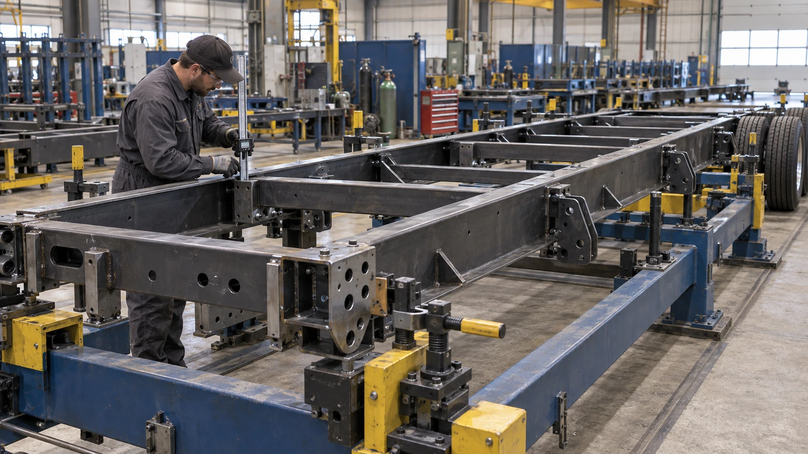
A laser-cut steel plate can leave the cutting machine with excellent dimensional accuracy. Its holes are positioned correctly. Its edges follow the CAD drawing. Its dimensions fall within the specified tolerances. The manufacturer bends it, places it in a fixture and welds it to the surrounding structure. After cooling, the finished component no longer fits. The mounting holes have shifted. A bracket is no longer square. Two telescoping tubes no longer align. A trailer frame that was correctly positioned during welding develops a slight twist after the clamps are released.
Nothing necessarily went wrong during laser cutting. The problem is that the dimensions of a finished welded assembly are not determined by cutting accuracy alone. Every subsequent manufacturing operation can change the geometry created by the previous one. Bending introduces forming variation. Fixturing establishes temporary positions. Welding creates highly localized heating and contraction. Cooling redistributes stress. Surface treatment and final assembly may introduce additional dimensional changes.
This is why a factory can own highly accurate laser-cutting and CNC equipment yet still manufacture components with inconsistent final dimensions. For trailer OEMs and procurement teams, the relevant question is not simply how accurately a supplier can cut steel. It is whether the supplier can preserve the required geometry through the entire manufacturing process. Precision is not a machine capability. Precision is a process-chain capability.
Engineering feature · Materials & Manufacturing
Uneven Heating and Shrinkage Change the Final Geometry
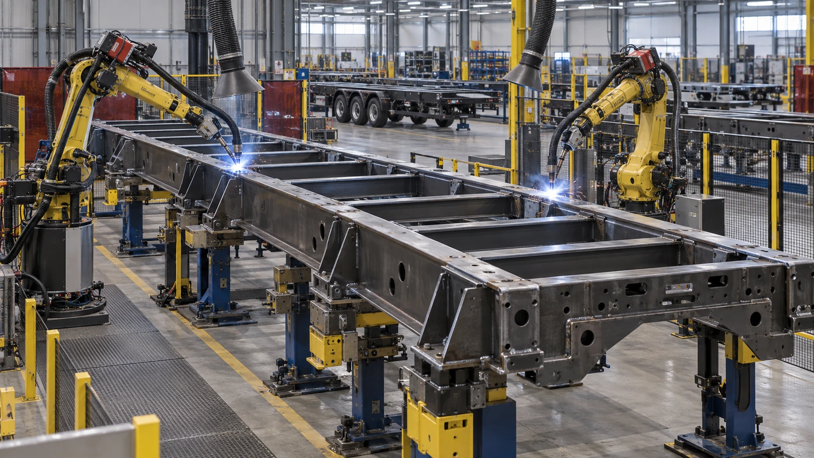
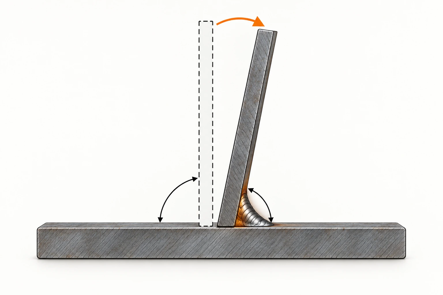
Welding changes the temperature of a component unevenly. The material immediately surrounding the arc becomes extremely hot. The steel farther away remains much cooler. The heated region expands, but its movement is constrained by the surrounding material. As the weld solidifies and cools, the weld metal and adjacent heated steel contract. The surrounding structure resists that contraction. The result can be residual stress, permanent deformation or a combination of both.
For example, consider a steel mounting plate welded to a rectangular tube. The plate is initially flat. The welder deposits a fillet weld along one side of the connection. As that weld cools, contraction on the welded side can pull the plate toward the weld. The plate may develop an angular deviation even though neither component was dimensionally incorrect before welding. The same mechanism appears on a larger scale in trailer beams.
Longitudinal welding can cause a beam to bow. Uneven welding around a cross-member can contribute to twist. Welding a bracket onto a relatively thin tube can produce localized distortion. The precise outcome depends on joint geometry, material thickness, heat input, restraint and welding sequence. The Welding Institute (TWI) explains these mechanisms [2] in its guidance on preventing welding distortion through structural and joint design. The central issue is not that welding makes steel permanently expand.
It is that localized heating, constrained expansion and subsequent contraction can leave the structure in a different shape after cooling. The finished geometry is the result of the entire thermal and mechanical history of the assembly—not merely the dimensions of its original parts.
A Cutting Tolerance Is Not a Finished-Assembly Tolerance
Laser cutting provides valuable advantages in trailer manufacturing. It can produce accurate profiles, repeatable holes and complex component geometries while reducing the need for secondary machining. That precision matters. Accurate components generally make fit-up easier and help manufacturers control joint gaps and fixture positioning. However, a cutting-machine tolerance describes a particular operation. It does not describe the completed assembly. Suppose a supplier advertises cutting accuracy of ±0.1 mm.
That is a hypothetical machine-capability example, not a universal specification for laser cutting. Even if the supplier achieves that accuracy consistently, the component may subsequently experience forming variation, welding shrinkage and coating buildup. The final mounting-hole position may therefore differ from the original cutting result. This creates several distinct measurements:
| Manufacturing stage | What should be controlled |
|---|---|
| Cutting | Profile dimensions, hole positions and edge condition |
| Bending | Final angle, bend radius and formed geometry |
| Fixturing | Component position, datum location and joint gap |
| Welding | Weld geometry, heat input, sequence and distortion |
| Cooling and release | Unrestrained straightness, flatness and positional accuracy |
| Surface treatment | Dimensional changes and coating-related clearances |
| Final assembly | Fit, alignment and functional performance |
A supplier that measures only the first stage cannot demonstrate compliance at the last stage. This does not make cutting accuracy unimportant. It makes it one part of a larger tolerance system. The manufacturing process should use accurate cutting to create a predictable starting condition, then preserve or compensate for dimensional changes during subsequent operations. The useful specification is not simply how accurately the machine cuts a plate. It is how accurately the finished component performs its intended function.
More Weld Metal Does Not Guarantee a Better Component
SSAB makes a particularly important observation in its trailer engineering guidance. In its Strenx trailer-design guidance, SSAB notes that welding distortion can be a more critical manufacturing concern than the static strength of the weld itself. Its guidance recommends minimizing unnecessary weld metal, controlling heat input, avoiding irregular root gaps, using symmetrical welds, compensating for shrinkage and optimizing welding sequence. These recommendations appear in SSAB's trailer-specific welding distortion guidance [1].
The statement requires careful interpretation. It does not mean weld strength is unimportant. A trailer weld must still satisfy the structural design and applicable acceptance requirements. Nor does it mean welding distortion is the governing engineering problem in every trailer structure. The point is that once an appropriately designed weld provides sufficient strength, adding more weld metal may not improve the finished component. It may create additional heat input and contraction.
That additional distortion can make the component harder to assemble or move critical mounting features outside their intended positions. Consider a jack mounting bracket. The specified weld may already provide adequate static load capacity. Increasing the weld size beyond the design requirement does not necessarily increase the useful capacity of the complete jack assembly. However, the additional welding can pull the mounting plate out of alignment.
The supplier may deliver a bracket with a large, visually impressive weld that is less compatible with the mating jack. The weld itself may be sound. The finished component may still be unacceptable. This is a critical distinction for procurement teams that use weld appearance or bead size as a shortcut for evaluating manufacturing quality. TWI recommends using the minimum specified weld size where appropriate as part of distortion control.
Its fabrication guidance [3] also discusses balancing welds, controlling tack-weld arrangements and selecting suitable welding sequences. However, reducing weld size below the required throat dimension is not an acceptable distortion-control strategy. The objective is to eliminate unnecessary weld metal, not necessary joint strength. This creates a direct relationship between structural design and manufacturing efficiency. Weld size should be sufficient for the intended load and joint requirements, but additional weld metal should not be mistaken for additional dimensional quality.
Welding Sequence Is Part of Manufacturing Design
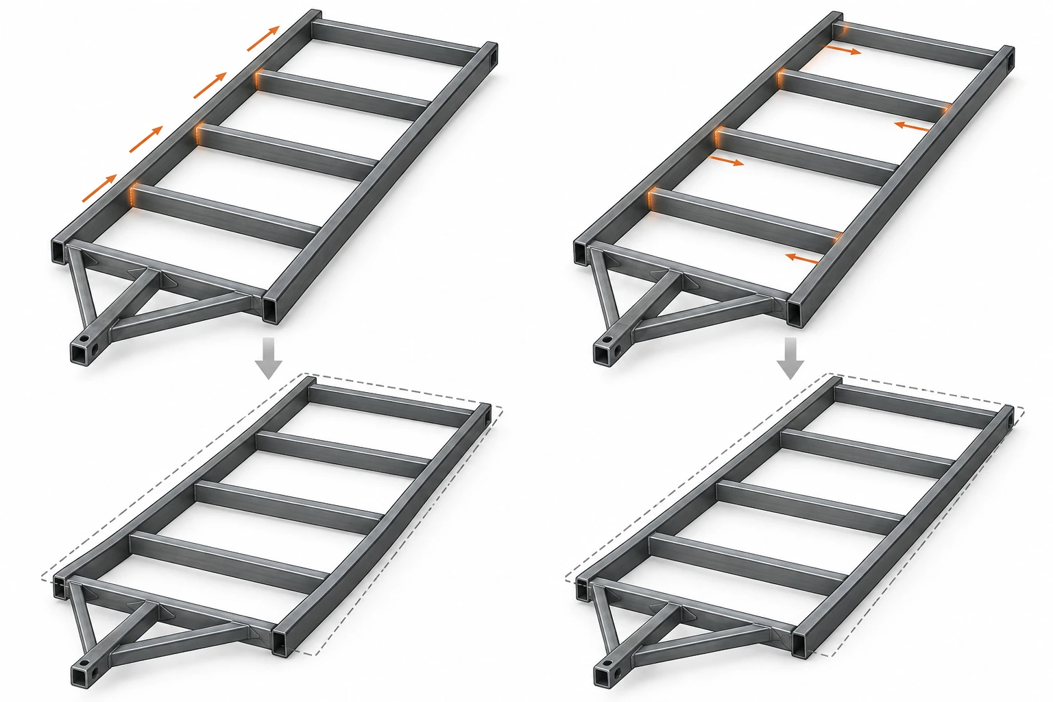
Two manufacturers can use identical steel, identical cut components and identical nominal weld sizes. Their finished frames may still have different dimensions. One reason is welding sequence. Consider a rectangular trailer frame containing two longitudinal rails and several cross-members. The fabricator positions the components in a fixture. The frame is initially square. Now imagine completing all the welds along one longitudinal side before beginning the opposite side.
As the first group of welds cools, their contraction can pull the structure toward that side. The opposite side may later produce a partially balancing effect. However, the final result depends on how the assembly was restrained, the order of heating and cooling, and the geometry that developed during the earlier operations. The second group of welds does not automatically reverse the first group's distortion.
An alternative process might distribute welding between opposite sides or different regions of the structure to control the accumulation of shrinkage. TWI identifies balanced welding, back-step welding and skip welding as possible distortion-control techniques. Its guidance also emphasizes welding sequence and progression toward free ends where appropriate. These are not interchangeable instructions that can be applied blindly to every trailer frame. The suitable sequence depends on the actual joint configuration, welding access and structural requirements.
But they demonstrate a fundamental principle: The welding sequence is part of the manufacturing design. It should not be left entirely to whichever order is most convenient for the individual operator.
Back-Step and Skip Welding
For a long weld, depositing the entire seam in one continuous progression can allow distortion to accumulate along the joint. Back-step welding changes the relationship between local welding direction and overall progression. Short weld segments are deposited in a direction opposite to the general progression of the work. Skip welding distributes weld segments along the joint in a planned sequence rather than completing one adjacent segment after another.
Both techniques can help control how shrinkage develops along a long connection. TWI describes these approaches in its technical guidance on distortion prevention through fabrication techniques [3]. However, the process must still provide the specified weld continuity, penetration and structural performance. An intermittent weld cannot replace a required continuous weld merely because it would reduce distortion. A back-step technique is not automatically appropriate for every welding process or joint.
The engineer must consider weld quality, fatigue-sensitive details, production access and applicable procedures. The correct question is: How can the required welds be deposited in an order that controls the final geometry? Not simply: Which welding technique produces the least heat?
Balance the Joint as Well as the Sequence
Another useful strategy is to balance welding around a structural member. Consider a beam with a vertical web and horizontal flange. If a weld is deposited on only one side of the web, its contraction can create an unbalanced force. The flange may rotate or bend toward the welded side. When suitable welds are arranged and deposited symmetrically, their contraction effects can partially counteract one another.
The result can be improved dimensional stability. TWI discusses balanced welding around the neutral axis as a method of controlling angular distortion. SSAB also recommends symmetrical welds in its trailer design guidance. For a trailer manufacturer, the engineering opportunity may extend beyond the welding sequence. The joint itself can sometimes be redesigned to produce a more balanced distribution of weld metal. SSAB provides an example involving the position of a beam web relative to its flange. Adjusting the web location can improve the relationship between the welds and the flange's neutral layer, reducing the tendency for welding-induced curvature.
The important lesson is not that every trailer beam should adopt one particular web position. It is that joint geometry and welding sequence can be designed together to control distortion. The geometry of the joint determines what happens after the parts have been cut.
Fixtures Control Position, Not the Entire Shrinkage History
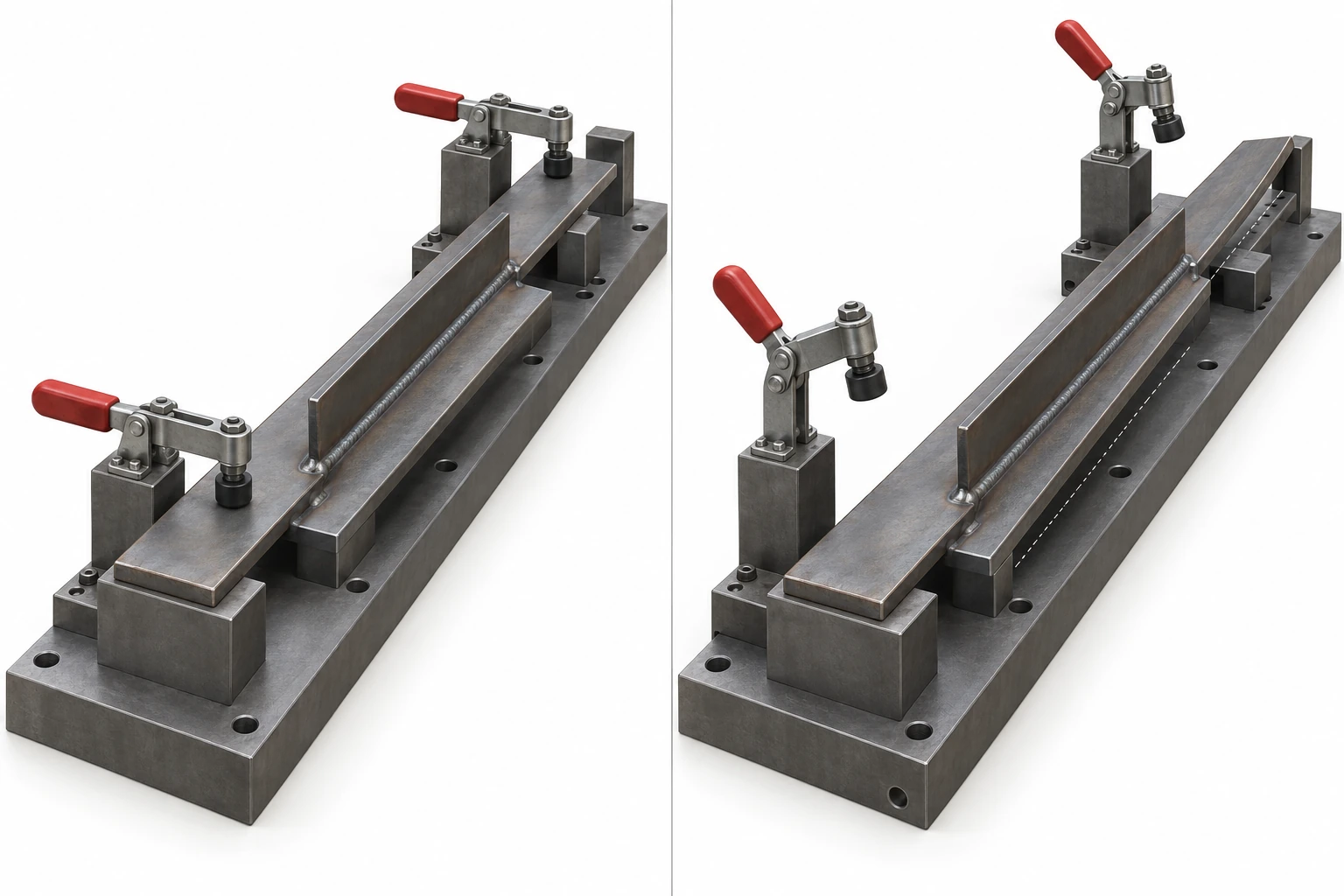
Welding fixtures are essential in volume trailer manufacturing. They establish component positions, maintain joint gaps and provide repeatable assembly conditions. A well-designed fixture can reduce operator variation and improve production consistency. However, a fixture does not eliminate welding shrinkage. It restrains movement while the component is held. If the weld creates significant residual stress, some deformation may occur after the clamps are released. Consider a long trailer bracket assembly held flat against a rigid fixture.
The welder completes the required connections. While clamped, the assembly appears straight. The quality inspector checks the accessible dimensions and confirms that the part is correctly positioned. The clamps are then removed. The component moves. The original inspection described the restrained geometry, not necessarily the free-state geometry of the finished part. TWI's guidance on pre-setting, pre-bending and restraint [4] explains that fixtures and clamps can help control distortion but may also generate significant restraint stresses.
Those stresses can increase the risk of cracking in unsuitable conditions. The solution is not to avoid fixtures. It is to design them as part of a controlled process. The manufacturer should know which dimensions must be established before welding, which movements are expected during cooling and which dimensions must be verified after release. A part that is straight inside the fixture is not automatically straight after manufacturing.
In some applications, pre-setting the component in the opposite direction of its expected movement can improve the final result. The assembly is deliberately positioned with a small, controlled offset before welding. After welding and cooling, the expected contraction brings it closer to the required final geometry. This is not permission to bend parts arbitrarily. Pre-setting must be established through engineering analysis, controlled trials or a validated manufacturing procedure.
The magnitude and direction of expected distortion should be known. The method must not compromise structural performance or introduce unacceptable residual stresses. The objective is to manufacture the required final shape predictably, rather than simply forcing the component to remain straight during welding.
Fit-Up and Tack Welds Set the Starting Conditions
Accurate cutting helps maintain consistent joint geometry. But the parts must also be positioned correctly before welding. The gap between mating components is particularly important. Suppose a cross-member is welded between two trailer chassis rails. The nominal cut length is correct. However, one rail is slightly bowed, or the fixture positions the members at a small angle. The joint gap may now vary along the connection.
The welder compensates by depositing more metal in the wider region. That area may require a different travel speed, additional passes or a change in welding technique. The thermal exposure becomes less consistent. As the joint cools, the resulting contraction can also vary along its length. This creates a causal chain: Fit-up variation → inconsistent weld volume and heat input → uneven contraction → dimensional variation.
The problem may appear to be welding distortion, but its root cause can begin earlier in assembly. SSAB's guidance on joint root gaps [5] explains that consistent joint gaps support reliable penetration and that controlling the gap can help reduce distortion. TWI also emphasizes that tack-weld sequence affects the ability to maintain a consistent gap along a joint. This is why a manufacturer should inspect fit-up before completing the weld.
A final dimensional problem cannot always be corrected by changing welding parameters alone. Sometimes the effective solution is a more accurate fixture, improved part preparation or a revised assembly sequence.
Tack Welding Is a Controlled Operation
Tack welds temporarily hold components in position before the main welding operation. They may appear to be a minor preparation step. In reality, their location, size and sequence can influence the entire fabrication. A small number of tack welds may allow a long joint to move as welding proceeds. The root gap may progressively close. Components can shift before the main weld is complete. Conversely, an excessive or poorly planned tack-weld arrangement may introduce additional heat and restraint.
TWI describes several tack-welding strategies for controlling gap closure, including approaches that begin near the center of a joint or use back-step progression. Its tack-welding guidance [9] emphasizes the relationship between tack placement, joint geometry and distortion. For trailer production, tack welding should therefore be treated as a controlled manufacturing operation. The procedure may need to establish tack locations, permitted fit-up conditions, sequence and how the tack welds are incorporated into the final connection.
This is especially important for long chassis members and repetitive bracket assemblies. A part should not rely on an operator manually pulling an inaccurate joint into position while depositing the main weld. That approach may produce acceptable results occasionally. It is not necessarily a stable production process. SSAB’s numerical root-gap recommendations are product-specific; they should not be transferred to every trailer joint. Fit-up, heat input and tack requirements must remain consistent with the qualified welding procedure. Tack welds incorporated into the final weld require the appropriate approved procedure and welder qualification; they are not exempt from weld-quality controls. [5] [9]
Where Small Distortion Becomes a Functional Problem
Frame Straightness and Inspection Datums
Frame straightness is an especially important example because small local changes can accumulate across a long structure. Consider a trailer frame consisting of two main beams and multiple cross-members. Each individual component may be within its cutting tolerance. Each cross-member may also be positioned correctly before welding. Nevertheless, local welding shrinkage can influence the final shape of the overall assembly. A main rail can develop bow.
A cross-member may pull one rail slightly inward. An asymmetrical attachment can contribute to local twist. If several of these effects occur along the frame, the overall geometry can deviate from the intended design. The significance depends on the frame's length, stiffness and functional requirements. A small local dimensional error may be unimportant in one area but significant near a suspension mounting location or coupling interface.
This is why the finished frame needs its own inspection requirements. Measuring individual cut parts does not establish final frame straightness. Likewise, measuring only the distance between the rails at one location may not reveal twist or longitudinal bow. The quality plan should identify the dimensions that control the actual trailer's assembly and operation. Depending on the design, those may include straightness, diagonal dimensions, mounting-point position and relationships between critical datums.
The inspection method must also define the condition under which the measurements are taken. A frame supported at different locations may show different elastic deflections. A meaningful dimensional report should therefore use an agreed support and measurement arrangement. Precision requires a defined final geometry, not merely a collection of accurate individual dimensions.
Suspension and Axle Mounting
Dimensional accuracy becomes particularly important around suspension mounting structures. The axle and suspension must be positioned relative to the trailer frame and its intended direction of travel.
A welded suspension bracket that moves during fabrication can affect the available adjustment range or the position of the installed suspension. This does not mean every axle-alignment problem originates in welding. Incorrect installation, worn components, loose fasteners, impact damage and other service conditions can also affect alignment. However, manufacturing geometry establishes the starting condition. Hendrickson's Trailer Axle Service Procedures [6] provide a useful trailer-specific reference. The manual addresses axle alignment relative to the trailer frame and identifies correct component positioning as an important part of installation.
The document also distinguishes alignment inspection from other issues involving bearings, suspension components and service condition. That distinction matters. A chassis manufacturer should not assume that an axle-alignment adjustment can compensate for any error in the underlying frame. Likewise, a manufacturing inspection cannot guarantee that the axle will remain correctly aligned throughout its service life. The OEM needs to control both the manufactured mounting geometry and the final installed alignment according to the relevant axle and suspension supplier's requirements.
This is where welding distortion can move beyond a factory rework problem. If critical mounting geometry is incorrect and cannot be properly adjusted, it can become a vehicle-level assembly and service issue. The relevant purchasing requirement is therefore not simply that the bracket was laser-cut accurately. It is that the complete mounting arrangement supports correct final axle installation.
Telescopic Jack Clearance
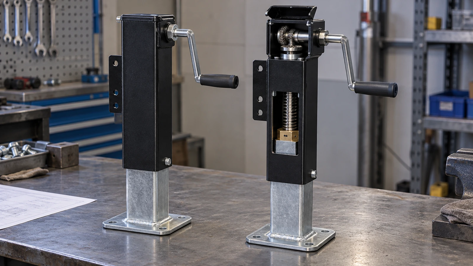
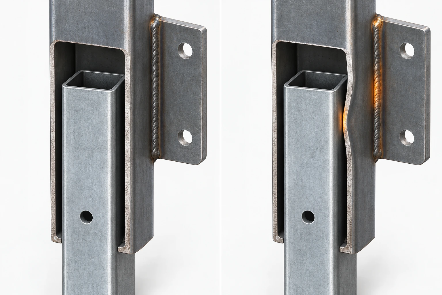
Telescopic trailer jacks provide another useful example. A jack may contain an outer structural tube and an inner moving tube. The components require suitable clearance and alignment to telescope correctly. For a round-tube design, the relationship between tube axes and concentricity may be relevant. For a square or rectangular design, parallelism, straightness, squareness and clearance are often more useful descriptions of the fit. Now consider a mounting plate welded to the outer tube.
Before welding, the tube may be straight. The mounting plate may have accurately cut holes. Both parts may satisfy their individual specifications. Welding introduces localized heating around the connection. If the welding arrangement is unbalanced, the tube may experience angular or local distortion. The outer tube can remain structurally sound while its internal geometry changes enough to affect telescoping. A small change in alignment may be significant when the original design has limited clearance.
Additional manufacturing operations can compound the problem. Coating buildup can change the available space between moving surfaces. Assembly variation can introduce another alignment error. The final mechanism may bind even though every individual part was initially manufactured within its nominal cutting tolerance. The relevant chain is: Tube geometry → forming tolerance → welding distortion → coating buildup → assembly clearance → telescoping performance. This illustrates why functional inspection can be more informative than a single dimensional measurement.
A jack tube that meets an external width requirement may still fail to telescope correctly. The completed component should be evaluated according to the function it must perform.
Mounting Interfaces, Not Just Hole Patterns
Mounting plates appear throughout trailer assemblies. They are used for jacks, equipment brackets, suspension components and other attachments. Their holes may be produced accurately by laser cutting or CNC machining. However, hole-position accuracy does not guarantee that the mounting surface will remain in the correct plane after welding. Imagine a plate with four mounting holes. The holes are correctly positioned relative to one another. The plate is welded to a structural tube.
As the weld cools, the plate develops a slight angular deviation. The hole pattern is still accurate within the plate. But the plate is no longer correctly oriented relative to the rest of the assembly. A mating component may become difficult to install. Fasteners may need to pull the components into contact. The assembled structure may contain unintended preload or local stress. The manufacturer might respond by enlarging the holes.
That may improve assembly, but it does not necessarily address the underlying dimensional problem. It may also change the original fastening design. The better response is to identify whether the error originated in forming, fixturing, welding or final assembly. The drawing should control the mounting interface relative to the datums that matter to the finished product. Hole diameter and spacing alone may be insufficient. This is an important procurement lesson.
A component can have an accurate hole pattern and still have an inaccurate mounting interface. Hendrickson’s L1061 manual is dated 2009 and is used here for alignment principles, not current numerical specifications. It specifically warns against bending an axle to correct alignment. Follow the applicable axle and suspension supplier’s instructions; generic straightening guidance is not permission to alter an axle. [6] For component selection, see GOODIN trailer jacks.
Accept the Finished Condition—Not Just the Weld Appearance
The manufacturing chain does not end when welding is complete. Surface treatment may introduce additional dimensional changes. For hot-dip galvanized steel, the zinc coating occupies physical space and the thermal cycle can influence distortion. For powder-coated steel, coating buildup may affect mating surfaces, holes and close-clearance features. The magnitude and relevance depend on the process and the component. These effects should not be assumed to be identical for different coating methods.
However, the underlying engineering requirement is the same. The final component needs to satisfy its dimensional specification after all required manufacturing operations. A bracket that meets tolerance before coating may no longer meet the intended assembly condition afterward. A telescopic tube may move correctly before coating but bind after the protective system is applied. A mounting plate may require a controlled masking or clearance strategy.
These requirements should be addressed during design. The manufacturer should avoid relying on uncontrolled grinding, drilling or forced assembly to correct predictable coating-related interference. Where post-coating machining is necessary, the process should include appropriate protection of any newly exposed surfaces. The correct acceptance point must therefore be explicit. Does a dimensional tolerance apply before coating? After coating? Or after final assembly? Different answers can produce different manufacturing and inspection requirements.
Set Functional Tolerances
The difference between part accuracy and weldment accuracy is recognized in engineering standards. ISO 13920:2023 [7] addresses general tolerances for welded constructions. It covers linear and angular dimensions as well as shape and position. The standard provides four tolerance classes based on customary workshop accuracy and explains that the relevant class should be selected according to functional requirements. It also states that the applicable tolerances are those specified on the drawing.
This is a useful distinction for trailer sourcing. A drawing may specify a tight tolerance for a laser-cut hole. That tolerance does not automatically establish the permissible distortion of the completed welded assembly. The OEM needs to define which dimensions control the finished product. Some features may require tighter control because they determine axle positioning, jack operation or mating-component alignment. Other dimensions may tolerate greater variation without affecting function.
Applying the tightest available tolerance to every feature is not necessarily economical. It can increase inspection effort, fixture complexity and rework without creating corresponding product value. Conversely, leaving critical dimensions undefined can allow unacceptable variation. ISO 13920 provides a framework for general welded-construction tolerances, but complex assemblies may still require specific dimensional and geometric requirements. The appropriate tolerance is the one required by the finished component's function—not the smallest number the factory can advertise.
Weld Inspection and Dimensional Inspection Are Separate
Visual welding inspection is important. It can identify surface discontinuities and help assess whether a welded joint satisfies applicable workmanship requirements. However, visual weld quality and dimensional accuracy are different properties. A weld may have an acceptable profile and no visible defects while the surrounding assembly is distorted. A bracket may be correctly positioned while the weld itself contains an unacceptable discontinuity. Both situations require different inspections.
ISO 17637:2016 [8] specifies visual testing of fusion-welded joints and can also be applied to inspection before welding. It does not replace the dimensional inspection of a complete trailer assembly. For OEMs, this distinction should appear in the quality plan. Weld acceptance should be verified according to the applicable welding requirements. Finished geometry should be verified according to the dimensional drawing and relevant inspection procedures.
Neither result automatically proves the other. This is especially important when suppliers advertise high-quality welding based primarily on bead appearance. A consistent-looking weld can be a positive sign of process control. But it is not a measurement of frame straightness, mounting-plate alignment or jack-tube clearance.
Control Correction, Do Not Normalize Rework
When a welded assembly distorts, the manufacturer may attempt to straighten it. Controlled correction can be an appropriate manufacturing operation in some applications. However, straightening should not become the default response to an unstable process. Mechanical correction can introduce additional deformation or residual stress. Thermal straightening introduces another heating cycle. For certain materials and structural details, those changes may require special consideration. A process that repeatedly produces distorted parts and then relies on extensive correction can also increase manufacturing cost.
The factory spends additional time handling, measuring and reworking components. The resulting geometry may vary according to the operator and correction method. For a fatigue-sensitive trailer structure, arbitrary heating or bending is particularly undesirable. The component's material properties, weld details and load path must remain acceptable. The most useful manufacturing response is therefore to investigate why the distortion occurred. Was the weld oversized? Was the sequence unbalanced?
Did fit-up vary? Was the fixture incorrect? Was the structure insufficiently supported? Did a material or thickness change invalidate the original procedure? Correcting the process can reduce the need for repeated straightening. Where correction remains necessary, it should be performed according to an approved method and followed by the required inspection.
Buy Repeatable Finished Geometry, Not a Machine Specification
A skilled fabricator may be able to produce one accurate trailer component through careful adjustment. The more difficult challenge is producing the same result repeatedly. Consider a manufacturer producing 1,000 welded jack mounting assemblies. The first prototype is accurate. Its tubes fit correctly, its mounting plate is aligned and the finished component passes inspection. During production, however, the fixture begins to wear. Incoming tube dimensions vary within their permitted tolerances.
A new operator uses a different welding sequence. The root gap changes. The manufacturer switches to a different material thickness. The original process may no longer produce the same final geometry. A factory can respond by adding more inspection and rework. But inspection does not create dimensional accuracy. It identifies whether the accuracy has been achieved. The production system must control the variables that generate the result.
For distortion-sensitive trailer components, this may require documented fixture settings, controlled welding sequences, appropriate process parameters and inspection at critical manufacturing stages. An OEM may also need to revalidate the process when the design, material or welding procedure changes. The objective is not to eliminate every possible source of variation. It is to control variation sufficiently that the finished component meets its functional requirements consistently.
Manufacturing precision becomes economically valuable when the factory can reproduce it without relying on exceptional operator intervention. For an OEM comparing suppliers, the lowest fabrication price may therefore not represent the lowest finished-component cost. A supplier with a stable welding process may produce fewer rejected parts and require less corrective work. That consistency can reduce total assembly effort even when the quoted unit price is not the lowest.
The relevant sourcing question is: How reliably does the supplier deliver components that meet the final dimensional requirements? Not simply: How accurately can the supplier cut steel? This is particularly important for repetitive trailer component manufacturing, where small process inefficiencies can accumulate across large production volumes.
Questions to Put in the RFQ
A sourcing specification should distinguish between equipment capability, component accuracy and completed-assembly accuracy. The following questions help translate dimensional requirements into useful supplier controls.
| Procurement question | Why it matters |
|---|---|
| Which finished dimensions are critical? | Define features that determine function and assembly compatibility. |
| Which tolerances apply before and after welding? | Separate cutting and finished-assembly acceptance. |
| Which inspection datums apply? | Measure the intended relationship between features. |
| How is fit-up controlled? | Control joint gaps, positioning and weld volume. |
| Is the welding sequence controlled? | Keep the thermal history and resulting geometry repeatable. |
| How are fixtures verified and maintained? | Detect locator wear and systematic positioning errors. |
| When are final dimensions measured? | Distinguish hot or restrained measurements from the specified finished condition. |
| What is checked after coating? | Verify finished clearances and mounting interfaces. |
| How is batch consistency demonstrated? | A successful prototype does not prove routine production capability. |
| Which corrective operations are permitted? | Protect structural integrity, material properties and coating protection. |
The RFQ should not require every supplier to use the same welding sequence or fixture design unless there is a specific engineering reason. Suppliers may use different validated manufacturing methods to achieve the same product requirement. The essential purchasing objective is to define the finished result and obtain sufficient evidence that the supplier can reproduce it consistently.
GOODIN View
Precision is not a machine capability. Precision is a process-chain capability. The value of accurate cutting is realized only when the subsequent manufacturing operations preserve the geometry needed by the finished product. A better trailer component is therefore not simply one that begins with a more accurate piece of steel. It is one that leaves the factory with the required dimensions, alignment and functional performance—and can be manufactured that way repeatedly.
That is the difference between owning precision equipment and delivering precision manufacturing.
For OEM trailer jacks and mounting interfaces, the useful qualification evidence is a controlled drawing, an agreed finished-state inspection plan and repeatable production results—not a cutting-machine specification alone. These controls must be demonstrated for the actual component and manufacturing route. Discuss your mounting datums, finished clearances and batch requirements with GOODIN.
Sources & Further Reading
Engineering context, not a universal welding procedure. Component drawings, material requirements, qualified procedures and applicable supplier instructions govern. Source editions are identified where relevant; no access dates are shown.
- SSAB — Welding distortion — Trailer design
- TWI — Distortion — Prevention by design
- TWI — Distortion control — Prevention by fabrication techniques
- TWI — Distortion — Prevention by pre-setting, pre-bending or use of restraint
- SSAB — The size of the joint root gap
- Hendrickson — Trailer Axle Service Procedures — L1061 (2009)
- ISO — ISO 13920:2023 — General tolerances for welded constructions
- ISO — ISO 17637:2016 — Visual testing of fusion-welded joints
- TWI — How can tack welding be used to minimise distortion?
Same Load Rating, Different Product: Why Two Trailer Jacks With the Same Specification Can Perform Very Differently
Aluminum Is Corrosion-Resistant—Until You Bolt the Wrong Metal to It: The Hidden Galvanic Problem in Trailer Assemblies
Related Article